Part Number: DP83822EVM
Hi team,
My customer is testing on DP83822EVM and they have several questions and need your help as below.
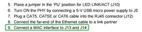
- Customers' system will not use TXCLK, 25M clk is provided by Ethernet Controller. According to EVM user guide, it shows that "need to connect a MAC interface to J13 and J14". With customers' needs, how could customers connect?

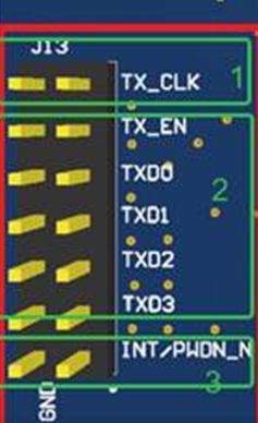
2. what kind of cables are used to connect TX_EN and TXD0-TXD3? What's the length? How to ensure a trace? (same question for thr Signal on J14).
3. Is INT/PWDN_N powered from EVM board? And smae connection requirements to question 2.
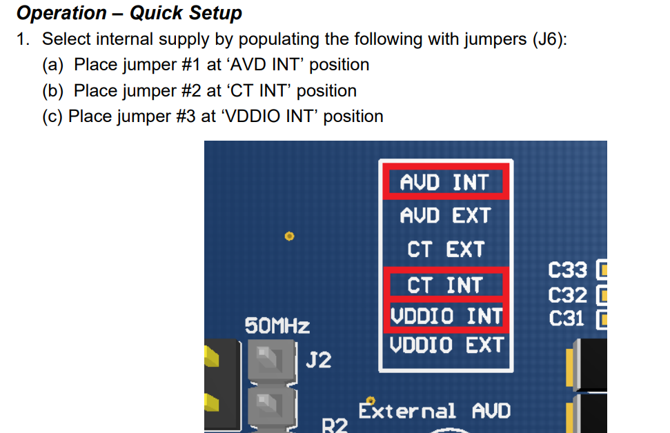
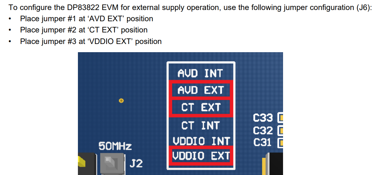
4. In the user guide, it shows can using external power and can use internal power, is it referring to choosing one of these?
Thanks.
Joyce