This thread has been locked.

If you have a related question, please click the "Ask a related question" button in the top right corner. The newly created question will be automatically linked to this question.

THVD2410: THVD2410 - RO shows additional data which is not on AB bus

Part Number: THVD2410

Hi Team,

We use THVD2410DR on multiple boards in one of our product, interfaced through RS485 (TTP). Along with TI part, we have other manufacturers as alternates

Currently facing issue in one of the production board which has TI part mounted. No issues with other manufacturers reported.

ISSUE: RO shows additional data which is not on RS485 AB bus (See image-1)
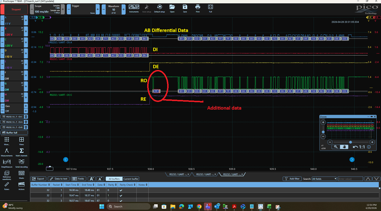
TI_Image-1.png

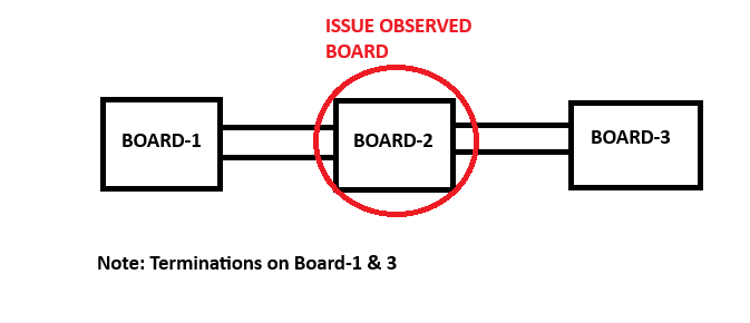
Setup shown below

TI_Image-2.png

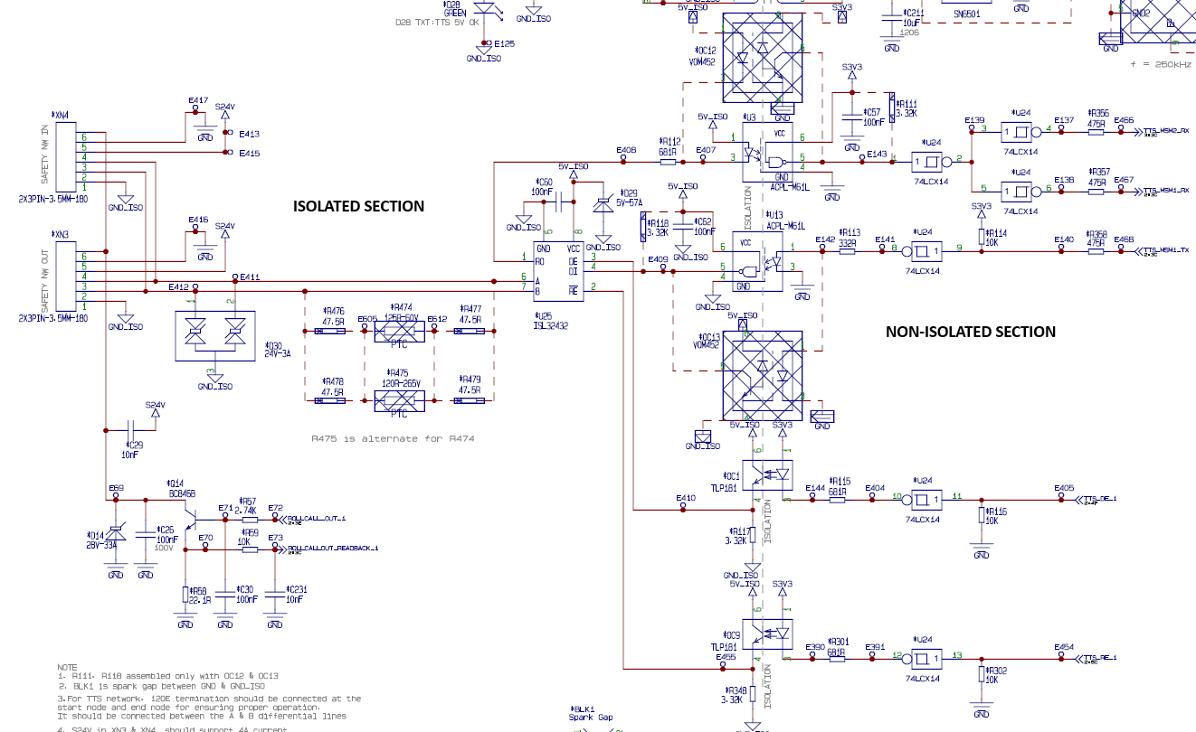
Schematics shown below

TI_Image-3.png

Few additional Informations:

  1. When trying to probe DE, RE on isolated section side, FF data not observed
  2. When trying to probe DE, RE on non-isolated section side, FF data observed continusely
  3. This FF data is observed in only one PCBA (TI part mounted). Not on all TI mounted PCBAs

Could you please support on this on high priority and help us to track the issue.

Let me know if any further details needed.

Thanks

ARFAJ

  • Hi Arfaj,

    Thanks for reaching out on E2E. Sorry to hear about this issue. 

    Could you measure the precise time that the R pin is driven low? 

    Can you also provide another waveform zoomed in on the glitch?

    From what I can see, this issue looks very similar to a common RS-485 glitch that can be present in any transceiver. Here is an app note about it in more detail (where THVD2410 is tested specifically): https://www.ti.com/lit/an/slla660/slla660.pdf 

    If the DE and RE pins are enabled separately, try adding a delay before enabling the RE pin.

    Best,

    Ethan

  • Hi Ethan,

    Thanks for the support

    Precise timing image when R pin driven low is shown below

    RE ON to Additional data FF - 36us

    Additional data Pulse width - 12us

    Hope images are ok now. Let me know if anymore details needed

    Additional Details:

    As i informed earlier, We have mounted more than 1000 units in field, this issue is observed in only 1 or 2 boards where TI part is mounted.

    Thanks

    Arfaj S

  • Hi Arfaj,

    Now that I am looking closer, I am seeing several inconsistencies with your waveforms. 

    You might have the A/B probes setup incorrectly. You either have them switched or the math function has the A-B math backwards. When D=high, A-B should be high. 

    Second, I see that when the DI line is toggling, and it is being reflected to the A/B pins. However, according to your waveform, DE is disabled. This does not make sense if the driver is disabled. 

    Additionally, the RE pin has inverted logic: /RE. In your waveform, when /RE goes high (meaning the receiver is disabled), we see the R pin toggle. Please double check your labels. 

    However, the ~10-12us time when R is low confirms it is the failsafe timer. There must be enough capacitance on the bus such that A/B differential voltage dips low enough to trigger the timer. The app note I linked directly applies to your situation. It looks like when the A/B pins drop to ~0V it briefly enters the undefined receiver region (VTH- < VOD < VTH+). 

    I would collect another waveform fixing the issues I mentioned, and zoom in on the A/B bus pins right at the time the R pin drops low. My guess is that high->low transition on the A/B pins either has some noise present or there is significant capacitance such that there is enough time for the failsafe timer to trigger. 

    One potential solution would be to enable your receiver after that A/B transition occurs (allowing the bus to dissipate). 

    Best,

    Ethan

  • Hi Ethan,

    My probing points are not at Transceiver end. As i said earlier,

    1. When trying to probe DE, RE on isolated section side, FF data not observed
    2. When trying to probe DE, RE on non-isolated section side, FF data observed continusely.

    For the above reasons, i have probed on below locations

    As requested, i have attached a zoomed image of AB at the time of FF data observed

    As you said earlier, i have added additional delay between DE disable and RE Enable. Increased delay from 2us to 35us. 

    Long run has been in progress. No additional data "FF" observed till now.

    Will update if any findings. Meanwhile let me know if there are any other findings at your end

    Thanks

    ARFAJ

  • Hi Arfaj,

    I think I misunderstood several things so thanks for clarifying. 

    Long run has been in progress. No additional data "FF" observed till now.

    Gotcha. I'll close this thread, but if you ever have more questions/issues, feel free to reach back out. 

    -Ethan