This thread has been locked.

If you have a related question, please click the "Ask a related question" button in the top right corner. The newly created question will be automatically linked to this question.

TCA39306: TCA39306: Question about using TCA39306 for I3C (1.2V <-> 3.3V) level shifting

Part Number: TCA39306
Other Parts Discussed in Thread: PCA9306

Hi,

I'm designing an I3C interface (1.2V to 3.3V) that needs to support up to 12.5MHz. I’m considering the TCA39306, but I ran into a few concerns and was hoping to get some advice here.

According to the datasheet, the TCA39306 doesn't support automatic switching between Open-Drain (OD)​ and Push-Pull (PP)​ modes. Since this chip requires external pull-up resistors for level shifting, I'm wondering:

  1. Is this chip still a viable option for an I3C application?

  2. If yes, how do I calculate the appropriate value for the external pull-up resistors?

    • Context:I've calculated the total load capacitance on both sides of the chip to be around 22pF. What should I consider next to determine the resistor values?

Any insights or suggestions would be greatly appreciated!

Thanks!

  • Hi Xujunfeng,

    The TCA39306 is a pass transistor solution. This requires pull-up resistors on both sides of the level translator. 

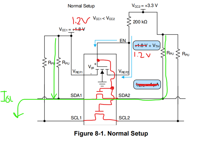
    For 1.2V to 3.3V, the device should be connected in "level translation mode" with pull-up resistors on side 1 and side 2. This is required even with integrated pull-up on the controller. 

    Is this chip still a viable option for an I3C application?

    It is viable, depending on your cap loading and systems requirements, you may have to use this device at a reduced data rate for I3C. 

    If yes, how do I calculate the appropriate value for the external pull-up resistors?

    • Context:I've calculated the total load capacitance on both sides of the chip to be around 22pF. What should I consider next to determine the resistor values?

    I would design for max pull-up resistance equal on both sides. 

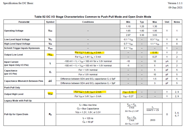
    I am referencing the I3C basic 1.1.1 spec. 

    Because TCA39306 is not a buffer, the sinking current on side 1 and side 2 will combine: 

    For example, if you choose 1k PU resistors on both sides, your effective sink current (assuming perfect drivers): 

    IOL = (1.2V / 1k) + (3.3V / 1k) = 1.2 mA + 3.3 mA = 4.5 mA

    4.5 mA is outside the I3C spec for VOL/IOL and VOH/IOH. The current should be limited to <2mA. Thus you may need to select resistors that are weaker depending on the driver characteristics on the I3C host controller and I3C target. 

    Regards,

    Tyler

  • Thank you for your previous response.

    I have a few additional technical questions regarding the TCA39306:

    1. Test Waveforms:​ Could you please share the test waveforms for the TCA39306 operating at I3C 12.5MHz with 1.2V to 3.3V level shifting? We want to evaluate the signal integrity under these specific conditions.

    2. Capacitance Parameter (Cio(on)):​ In the datasheet, the parameter Cio(on)​ is specified as 10.5 ~ 12.5pF. Is this value measured per-side​ (single channel) or is it the combined capacitance​ of both sides of the same channel (e.g., SDA1 to SDA2)?

    Thank you for your continued support.

  • Hi Xujunfeng,

    Test Waveforms:​ Could you please share the test waveforms for the TCA39306 operating at I3C 12.5MHz with 1.2V to 3.3V level shifting? We want to evaluate the signal integrity under these specific conditions.

    Ti.com sells the TCA39306EVM, would you have the necessary equipment to test I3C 12.5MHz using the EVM from 1.2V to 3.3V? 

    Capacitance Parameter (Cio(on)):​ In the datasheet, the parameter Cio(on)​ is specified as 10.5 ~ 12.5pF. Is this value measured per-side​ (single channel) or is it the combined capacitance​ of both sides of the same channel (e.g., SDA1 to SDA2)?

    CIO(ON) = 12.5pF is the maximum capacitance seen by the I/O through the pass FET. It includes the capacitance from both sides of the device.

    Regards,

    Tyler

  • Hi Tyler,

    I'm comparing the PCA9306DCUR​ and the TCA39306DCUR. They look almost identical—both are pin-to-pin compatible and use a MOS structure for bidirectional level shifting.

    However, I noticed that their frequency specifications are quite different. If they both use MOSFETs, why does the TCA39306 support much higher frequencies (like I3C speeds up to 12.5MHz) while the PCA9306 is generally limited to standard I2C speeds?

    Does anyone know the specific internal differences or improvements made in the TCA39306 series?

  • Hi Xujunfeng,

    The PCA9306 was developed in 2004 under a different process which limited performance characteristics such as Ron, prop delay, etc. 

    TCA39306 is the updated, improved spec, allowing faster data rates, higher bandwidth. 

    From a design perspective, they have the same structure, pass transistors connecting side 1 to side 2 and including a reference FET between VREF1 and VREF2. 

    Regards,

    Tyler