This thread has been locked.

If you have a related question, please click the "Ask a related question" button in the top right corner. The newly created question will be automatically linked to this question.

LMH1219: LMH1219 configuration for 6G-SDI

Part Number: LMH1219
Other Parts Discussed in Thread: TIDA-00428,

Dear Team,

I have one SDI to Optical desing same as TIDA-00428  referance desing,
i have some issue when i connect 6G-SDI camera on my POC board .

6G-SDI input from camera to LMH1219 not working - HEO and VEO - 0 so issue at Out0 not matching eye diagram requirement .

when i connect PC monitor with 3840x2160 HDMI to 6G-SDI converter and to LMH1219 its workgin and gives proper HEO and VEO reading and all work .
some time it gives short flicker on video .

any idea what could be the reason ?
i have simple configuration 

//////////////////////Select IN0 and override pins/////////////////

// CTLE/CDR page

lmh1219_i2c_write(0xFF, 0x04);

// Override IN_OUT_SEL → force IN0

lmh1219_i2c_write(0x3F, 0x10);

// Override OUT_CTRL

lmh1219_i2c_write(0x3F, 0x08);

// Override reference rate

lmh1219_i2c_write(0x3F, 0x04);

// Enable IN0 → OUT0 only

lmh1219_i2c_write(0x31, 0x01);


//////////////////////


//////////////Enable OUT0 driver/////////////

// CableEQ/Driver page

lmh1219_i2c_write(0xFF, 0x05);

// OUT0 power‑down override ON

lmh1219_i2c_write(0x31, 0x20);

// OUT0 enabled (power‑down = 0)

lmh1219_i2c_write(0x31, 0x00);


///////////////////////////////////////////////


/////////////////////////////////Reset Cable EQ acquisition/////////////

lmh1219_i2c_write(0x19, 0x04);

lmh1219_i2c_write(0x19, 0x00);

//////////////////////////////////////////////////////////////


////////////OUT0 tuning (VOD + DEM)///////////////////////

// Still on page 0x05


// ---- VOD = 7 (max) ----

uint8_t r30;

lmh1219_i2c_read(0x30, &r30);

r30 |= (1 << 5); // VOD override enable

r30 = (r30 & ~0x07) | 0x07;

lmh1219_i2c_write(0x30, r30);


// ---- DEM = 0 dB ----

uint8_t r31;

lmh1219_i2c_read(0x31, &r31);

r31 |= (1 << 6); // DEM override enable

r31 = (r31 & ~0x07) | 0x00;

lmh1219_i2c_write(0x31, r31);


///////////////////////////////////////////////////


/////////////Enable reclocked data on OUT0/////////////////////

// CTLE/CDR page

lmh1219_i2c_write(0xFF, 0x04);


// Reclocked data on OUT0/OUT1

lmh1219_i2c_write(0x1C, 0x08);


// SMPTE lock enable

lmh1219_i2c_write(0x2F, 0x00);


// Reset CDR

lmh1219_i2c_write(0x0A, 0x0C);


// Release CDR reset

lmh1219_i2c_write(0x0A, 0x00);


/////////////////////////////////////////////


/////////////Disable EQ bypass//////////////

// CableEQ/Driver page

lmh1219_i2c_write(0xFF, 0x05);


// Disable EQ bypass override

lmh1219_i2c_write(0x27, 0x00);


////////////////////////////////////////////

lmh1219_i2c_write(0x33, 0x30); //Power down OUT1

////////////////////////////////////////////


any idea about the issue ?

Regards,
Nikunj


  • Nikunj

    Can you please share your schematic and layout for review?

    Instead using I2C to configure LMH1219, can you switch to pin strap mode? Are you still seeing the issue in pin strap mode? Does the LOCK_N also go low to indicate a lock condition?

    Thanks

    David

  • Dear David,

    i try with strap mode Lock_N - low in both case we have Lock - problem is some time flicker comes , i make test for multiple times if i have proper video without flicker it will work as expected but some time it gives flicker when i turn off and on again , i think there is some issue with 6G-SDI signal because when i use some other device with SDI loop out it works as expected i must order one converter and evaluate this and will inform you .
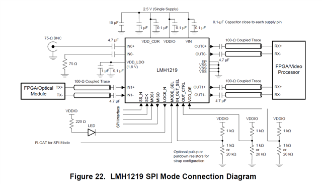
    refer below schematic - i had some issue on LMH1219 - VDD_LDO pin i must not connect this to 2.5V .


    Regards,

    Nikunj

  • Dear David,

    i just perform test with 2 different setup - 

    Setup 1 - 

    PC HDMI 2560x1440 30Hz resolution feed to HDMI to 12GH SDI converter - SDI connect to our design and its working ..
    [MAIN][INF] HEO raw = 0x1F →  UI
    [MAIN][INF] VEO raw = 0x75 →  mV
    [MAIN][INF] Carrier Detect: 0xE2
    [MAIN][INF] EQ coarse done: 0x41
    [MAIN][INF] OUT0 VOD reg : 0x2F
    [MAIN][INF] OUT0 DEM reg : 0x40
    [MAIN][INF] CDR lock + VCO bits: 0x5C

    Setup 2 - 

    Camera module - https://www.jencam.de/en/products/cameras/zoom-cameras/fcb-er8530-fg-6g-sdi-in-housing
    it FCB-ER8530 camera and HDMI to SDI converter board TV10 0080 .
    this setup not working 

    [MAIN][INF] HEO raw = 0x10 →  UI
    [MAIN][INF] VEO raw = 0x15 →  mV
    [MAIN][INF] Carrier Detect: 0xE2
    [MAIN][INF] EQ coarse done: 0x41
    [MAIN][INF] OUT0 VOD reg : 0x2F
    [MAIN][INF] OUT0 DEM reg : 0x40
    [MAIN][INF] CDR lock + VCO bits: 0x5C

    after using external converter for EQ/reclock 

    [MAIN][INF] HEO raw = 0x2D →  UI
    [MAIN][INF] VEO raw = 0x81 →  mV
    [MAIN][INF] Carrier Detect: 0xE2
    [MAIN][INF] EQ coarse done: 0x41
    [MAIN][INF] OUT0 VOD reg : 0x2F
    [MAIN][INF] OUT0 DEM reg : 0x40
    [MAIN][INF] CDR lock + VCO bits: 0x5C


    any idea what i can do in setup 2 without external converter , is there any tuning for SDI in to achieve suitable result ?

    Regards,

    Nikunj 

  • Dear David ,

    i change the termination , at IN0+ remove the 75Ohm pull down and IN0- 75ohm to GND and now i able to make it work with camera ,

    thank you for your support,

    Regards,

    Nikunj