Other Parts Discussed in Thread: TUSB2077A
I'm having some trouble getting the TUSB2077A hub to work.
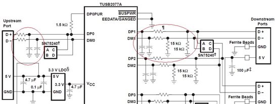
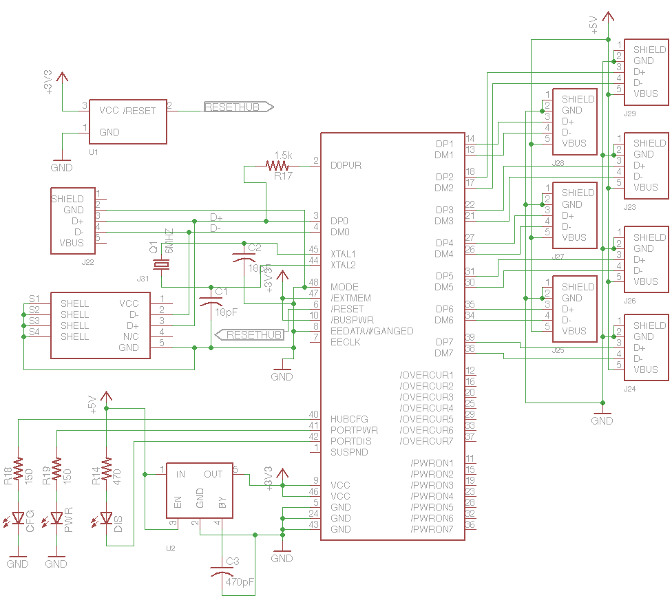
My schematic is shown below. It's a close copy of the reference diagram from p13 of the datasheet. This is to be used in an "installed once" setup, so I don't need power management for the ports of the hub. There are a few additional differences that I don't think would cause the behavior I'm seeing (described below)
When I power up the circuit, I'm able to confirm:
- The clock oscillates at 6MHZ
- There is 3.3v on all power pins
- reset is high
All that being the case, when I plug it into my host computer, nothing happens (windows doesn't indicate it's detected a new device, the hub I connect it to doesn't illuminate to indicate the device has been enumerated, etc.)
Any thoughts as to what could be going or where to start with debugging? The chip is a bit of a black box and i'm not sure what signals I can probe to deduce what could be happening.
Thanks!
-kailas