Part Number: TMDS181
Hello Interface Forum Team,
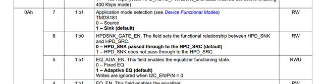
We are experiencing a critical field interoperability issue with a mass-produced product utilizing the TMDS181 in local I2C register control mode. By default, the device is configured to run in Full Retimer Mode with Adaptive EQ enabled.
To resolve site-specific compatibility bugs with older and newer source devices, we are implementing a firmware-level dynamic fallback mechanism.
Upon signal detection, our MCU starts a firmware timer. If the link fails to achieve a stable lock or fails to complete adaptive equalization within a 100ms to 150ms timeout window, the MCU must check the precise incoming TMDS clock frequency and execute a dynamic fallback based on the clock parameters.
Could you please provide the official, silicon-verified instructions for the following requirements?
1. TMDS Clock Counter Registers & Frequency Conversion Formula (EyeScan Equivalent)
-
We need to measure the actual frequency of the incoming TMDS clock to choose the correct fallback path (separating 1080p60 at ~148.5MHz from 4K60Hz at 297MHz/594MHz).
-
Please provide the exact internal clock counter register addresses and the mathematical conversion formula/equation to calculate the actual TMDS Clock frequency (in MHz) from those raw values, exactly as counted and displayed in the TI EyeScan control software.
2. Status Monitoring Registers for Adaptive EQ and Link Lock Failure
-
Which specific status registers and bit combinations should the firmware poll to reliably distinguish a failed/abnormal link state from a stable one within the 150ms window? We need the exact bits that indicate signal detection is active, but adaptive EQ or the CDR/Channel lock has failed to stabilize.
3. Precise Sequence to Halt/Freeze the Ongoing Adaptive EQ Loop
-
When Adaptive EQ fails to converge, we must immediately halt the automatic routine before applying manual parameters.
-
What is the exact step-by-step I2C sequence to completely freeze and terminate the internal automatic adaptive equalization state machine?
4. Transition Sequence to Fixed EQ Mode (7.5dB Mid-range)
-
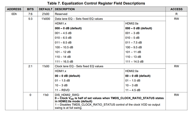
After freezing the adaptive loop, we need to force Fixed EQ mode with a 7.5dB setting.
-
Please provide the precise register address and safe bitmask to force Fixed EQ and select the Mid-range value without corrupting critical default bits.
-
Which specific register bit must be toggled immediately afterward to initiate an instantaneous CDR re-lock based on the newly applied manual fixed EQ values?
Since our customer's site operations are severely impacted, your prompt guidance on the exact register access sequences and formulas based on the true silicon architecture is highly appreciated.
Thank you in advance for your support.
Best regards,