DP83848H: Ethercat topology discussion

Part Number: DP83848H
Other Parts Discussed in Thread: DP83822EVM

Hi team,


I'm posting on behalf of the customer. Could you please see below question?

This is Paul from Greenlight.  I’m reaching out on a separate topic for the same project.

While reviewing TI application note 1519, I came across figure 10 below.


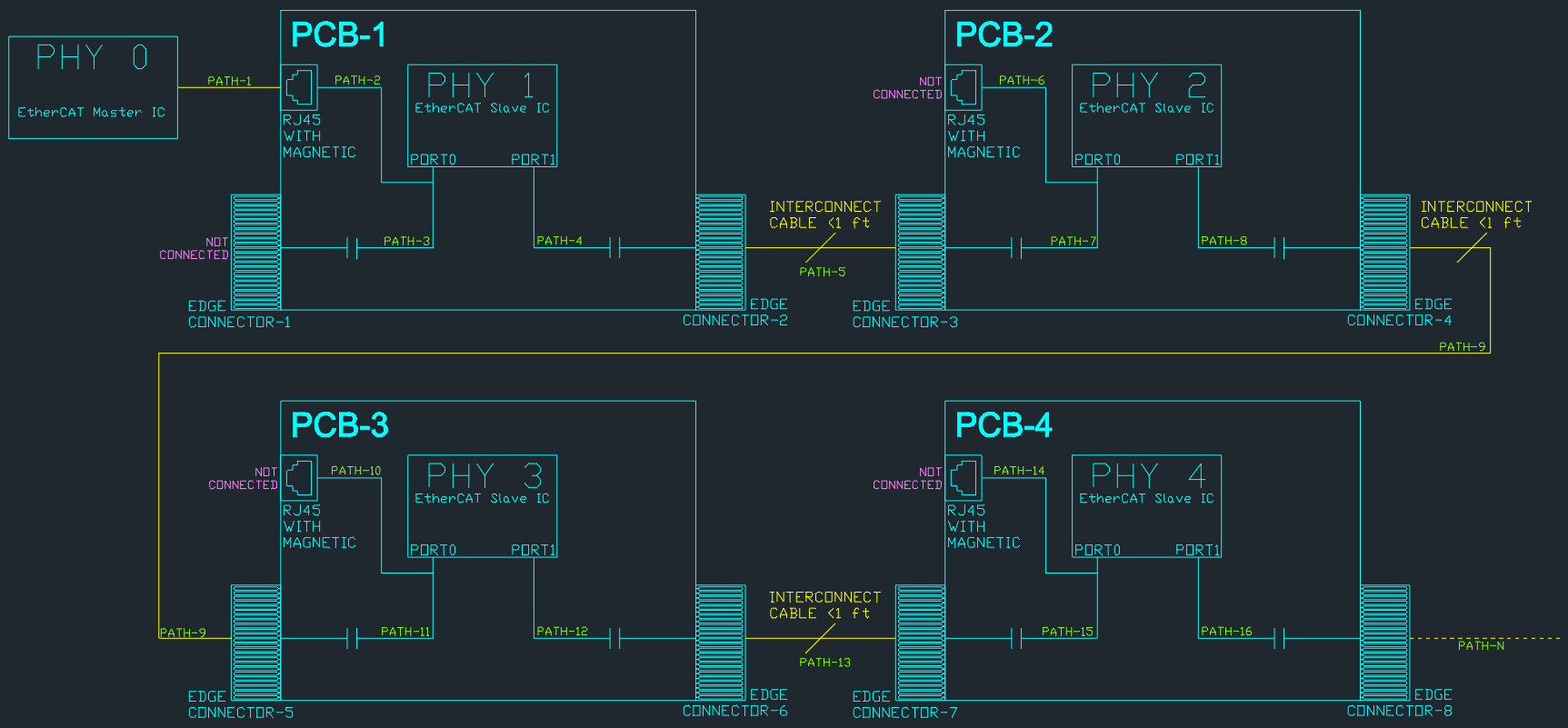
The transformerless topologies shown in the figure make sense to me. However, I was wondering whether the topology below would also work.

Essentially, this is similar to topology C from Figure 10, but with a digital switch added to one of the PHYs. The switch toggles between one of the PHYs and an RJ45 connector with integrated magnetics.

In this configuration, would the transformerless implementation between PHY1 and PHY2 still work properly, or would the added switch compromise the design?


Would you be able to answer my question or point me to someone who is familiar with transformerless Ethernet/EtherCAT design?

  • Hi Shaury,

    Can I get a few clarifications on the intended design:

    • Is the intention to either connect the RJ45 to PHY 1 or PHY 2? In this case there could be issues with the signal path having both the magnetics of the RJ45 and the capacitors when RJ45 is connected to PHY 2.
    • What switch will be used?

    Best regards,

    Greg

  • Hi Gregory,

    Thanks for your explanation. I’m the customer Shaury was referring to in his post.

    As I understand it from your first point, an EtherCAT/Ethernet signal path should not contain both an RJ45 with magnetics and a transformerless capacitive coupling path on the same line. Is my understanding correct?

    Attached drawing is a more detailed overview of our current system:

    • PCB-1, PCB-2, PCB-3, and PCB-4 are all identical.
    • Only PCB-1’s RJ45 is used to connect to PHY0 on the EtherCAT master.
    • Only PCB-1’s left edge connector (EDGE CONNECTOR-1) is not connected.
    • The RJ45 connectors on all subsequent PCBs are not connected.
    • The EtherCAT path for all subsequent PCBs goes through the edge connectors and board-to-board interconnects.

    The part I am unsure about is whether we can implement the transformerless coupling capacitors (according to TI's AN-1519) together with the RJ45 path as shown in the drawing, knowing that only one path is used at any given time. (i.e. If the RJ45 is used, the edge connector at PORT 0 is not connected. If the edge connector at PORT 0 is used, the RJ45 is not connected.)

    Or do we need to physically disconnect the path between the RJ45 and edge connector using a digital switch, even if only one path is used at a time? For example, if only the RJ45 is used and EDGE CONNECTOR-1 is not connected, would we still need a switch to physically disconnect PATH-2 and PATH-3? Same goes for the subsequent PCBs, if RJ45 is not used, do I need to physically disconnect PATH-6 & PATH-7, PATH-10 & PATH-11, PATH-14 & PATH-15, etc.?

    Also, we have the option to DNP the transformerless coupling caps on PATH-4, PATH-8, PATH-12 and PATH-16. In your opinion, is it better to keep the caps in or DNP them? 

    Paul Chen

    Greenlight Innovation

  • Hi Paul,

    Thanks for the clarification. I do think the drawing of your system did not attach. Can you please try resending it?

    Best regards,

    Greg

  • Hi Greg,

    Sorry about that. For some reason, the E2E platform only allowed me to use image URLs and would not let me upload images directly.

    Here is the image url: https://i.postimg.cc/Td75SVs0/system.png

    Paul

  • Hi Paul,

    It seems this link is also blocked by the TI system. Can you put the .png file in a zip folder and attach it to your response? Let me know if that works, thanks!

    Best regards,

    Greg

  • Hi Greg,

    I have attached the diagram in the ZIP file. Please let me know if you are able to view it.

    daigram.zip

    Thanks,

    Paul

  • Hi Paul,

    This file works great, thanks. I will review it as soon as possible and provide comments. 

    Best regards,

    Greg

  • Hi Greg,

    Much appreciated. Glad to hear it worked.

    Paul

  • Hi Gregory,

    Just wanted to check in and see if you've had a chance to review the file yet. Any feedback or comments would be appreciated when you have a moment.

    Sincerely,
    Paul

  • Hi Paul,

    This design looks to be the correct implementation. We recommend physically disconnecting the path between the RJ45 and the edge connector when not in use.

    In our DP83822EVM, we do something similar with a passive component to select between transform and transformerless topology. In your design, the most important point is the selection of the switch that will ensure the two paths are clean. However, we have not created a design of this exact type before and therefore do not have a switch recommendation to make. 

    Best regards,

    Greg

  • Hi Gregory,

    Thank you for your reply. It was very helpful. Based on the feedback received, we have decided to move forward with a passive implementation similar to the DP83822EVM instead of using a switch.

    Sincerely,
    Paul

  • Hi Paul,

    Thanks for the update, glad I could help.

    Best regards,

    Greg