This thread has been locked.

If you have a related question, please click the "Ask a related question" button in the top right corner. The newly created question will be automatically linked to this question.

DP83826I: Crystal Drive Level

Part Number: DP83826I
Other Parts Discussed in Thread: DP83826EVM

Hi 

I can’t find in the ETH PHY DP83826 datasheet the Crystal Drive Level.

What is the DP83826 Crystal drive level [µW]?   

I found in document  Selection and specification of crystals for Texas Instruments ethernet physical,

that - you can use 100 [µW] crystal drive level Max , BUT the recomandation is to add serial resistor. 

I'm want to avoid a new layout because of the recommendation to add a resistor. 


I’m going to use crystal ECS-250-18-33-JGN-TR3 , please advise if it suitable for DP83826?


Please if possible, send me documentation contains the Drive Level requirements.

Thanks 


Regards 

Nir  

  • Hi Nir,

    The specs on that crystal are ok to use with DP83826.

    As far as drive level is concerned, are you able to populate a 0-ohm resistor on the board then tune as needed when the design is available to test? I am not aware of any characterization done on the oscillator amplitude of DP83826 so this is something where test and measurement would be best.

    If you want a rough idea of the PHY performance before designing the board, consider using the DP83826EVM as a test platform. This board comes with a crystal and space for a limiting resistor that is default 0 ohms.

    Best,

    Shane

  • Hi Shane 

    Thanks for your response,
    I am currently at the stage with an existing board but without a resistor option in the crystal circuit and I have a few questions:
    If the crystal I included is suitable for the DP83826 why do I need to add a resistor?
    Is adding a resistor mandatory?
    I want to avoid adding a resistor... am I missing something basic?
    If I put an oscillator with 500uW MAX will that eliminate the need for a resistor?
    Additionally, if I perform measurements as you mentioned, are there no tolerances between the PHY components?

    Please advise


    Regards

    NiR

  • Hi Nir,

    If the crystal I included is suitable for the DP83826 why do I need to add a resistor?

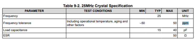
    The crystal has the correct specs for ppm, frequency and load capacitance such that It fits this table in our datasheet:

    This means that the PHY can work with this crystal. The resistor is more for ensuring long term reliability of the crystal rather than a spec needed for the PHY. 

    Is adding a resistor mandatory?

    No it is not mandatory. You will notice that on our EVM we leave the series resistor 0-ohm and the board still works.

    I want to avoid adding a resistor... am I missing something basic?

    The resistor is not mandatory, but it does help prevent the crystal from exceeding its maximum drive level. Exceeding the drive level may degrade the crystal over time, though you may want to ask your crystal manufacturer what the implications of this are.

    If I put an oscillator with 500uW MAX will that eliminate the need for a resistor?

    An oscillator should not need a series resistor because there is no feedback path from the PHY to the oscillator

    Additionally, if I perform measurements as you mentioned, are there no tolerances between the PHY components?

    Seeing as this is not a characterized spec, it is difficult to say what tolerance the PHY would have. If factoring in tolerance it would be a good idea to measure a sample size of PHYs or to add margin for the drive level of the crystal into the resistor value. For the measuring procedure itself I recommend talking with the crystal manufacturer as they likely have more experience with this sort of measurement.

    Best,

    Shane

  • Thanks Shane, 

    I measured on my design the Vpp on CL1 by KEYSIGHT N2795A Active Probe 1.0pF with scope channel on 50Ω, and its 1.73Vpp - is that normal value? 

    I also calculate the Drive Level according to the Vpp I measured and to the below formulas: 

    Iqrms =(2*3.141592*F)*Ctot*(Vpp/(2*SQRT(2)))

     DL =Iqrms ^2*ESR

     Ctot = CL1 + Cs + Cprobe  = 33pF + 3pF +1pF= 37pF

    *CL1 = 33pF because ppm calibration

    the DL calculation results: 512.2uW

    The DL is way to high ! 

    Is the calculation correct? what are you suggesting ?  please advice 

    Regards 

    Nir  

  • Hi Shane, 

    about the EVM, can you please share the EVM Crystal component and parameters? there is no information in the EVM schematic sheet.

    Thanks 

    Nir 

  • Hi Nir,

    The EVM crystal is ECS-250-12-33Q-JES-TR

    That peak voltage would be within the spec for the XI input, so this is ok:

    Calculating the drive level is a process I strongly recommend reaching out to the crystal manufacturer for information on. While we have a general suggestion on how to limit overdriving the crystal, performing measurements/calculations is not something our team has experience with since this is more of a crystal concern than a PHY concern.

    Best,

    Shane