Part Number: TCAN2451-Q1
Hello
TCAN2451-Q1 Power ON, VCC2 voltage down to 4.12V, then recover to 5V.
Question: Why VCC2 down to 4.12V? Is it a normal operation mode?
The test waveform as below:
CH1~CH4: VCC1/RST/VSUP/VCC2
This thread has been locked.
If you have a related question, please click the "Ask a related question" button in the top right corner. The newly created question will be automatically linked to this question.
Part Number: TCAN2451-Q1
Hello
TCAN2451-Q1 Power ON, VCC2 voltage down to 4.12V, then recover to 5V.
Question: Why VCC2 down to 4.12V? Is it a normal operation mode?
The test waveform as below:
CH1~CH4: VCC1/RST/VSUP/VCC2
Hi Eason,
Can you share your schematic showing what all is connected to VCC2 and VSUP and what the load current is at the time of the dip? You might not have enough output capacitance.
Regards,
Matt
Hi Eason,
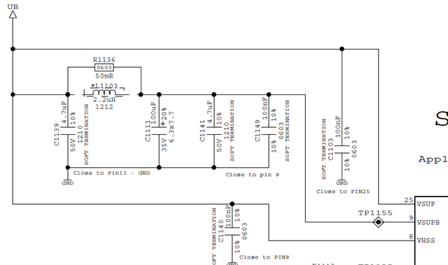
Thanks for sharing. If the only things connected to VCC2 at the time of this measurement are what is shown in your screenshot, it is still technically loaded since you have a 1kOhm resistor sinking 1mA of current to GND. Not sure why that is needed, but it will hurt your overall power consumption of your system. If you are using it to provide a discharge path to GND for the output capacitors when VCC2 turns off, I would use a 100kOhm resistor instead to improve overall power efficiency .
Two more things that jump out to me:
1.) On VSUPB, L1103 seems to be un-populated and you have R1136 (50mOhm) populated instead. You need to have this inductor for the pi-filter on the input of VSUPB for the device to work properly. VSUPB is the input to the buck regulator which is constantly fluctuating in current. The pi-filter is meant to separate any ripple cause by this fluctuation from the VSUP and VHSS power ports. That might not be causing the drop in VCC2 that you're seeing, but it is still a change I recommend you make. Refer to Figure 10-7 and Table 10-1 in the datasheet.
2.) VCC2 doesn't start ramping until about 50ms after VCC1 and nRST go high (device in Standby/Normal mode). By default, VCC2 and VCC1 should start ramping at the same time, which tells me you have something in your code that keeps VCC2 off at startup and then turns it on later. Is that correct?
I'm thinking there might be a something in your code that is unintentionally turning off VCC2 temporarily at the time of the dip and then turning it back on quickly. Can explain the flow of your code with regards to VCC2 and also provide a read-out of the interrupt registers to see if there is something getting flagged?
Also, does this dip in voltage happen at the same spot every time, or does it vary? Also, is this event only being observed on only one device or is it repeatable on multiple devices if you swap them out?
Regards,
Matt