TUSB4041I: TUSB4041I not setting the PWRCTL1..4/BATEN1..4 outputs correctly upon reset deassertion

Part Number: TUSB4041I
Other Parts Discussed in Thread: LP3961

Hi team,

I struggle to help my customer here as I don't have expertise on USB, see following description from customer:

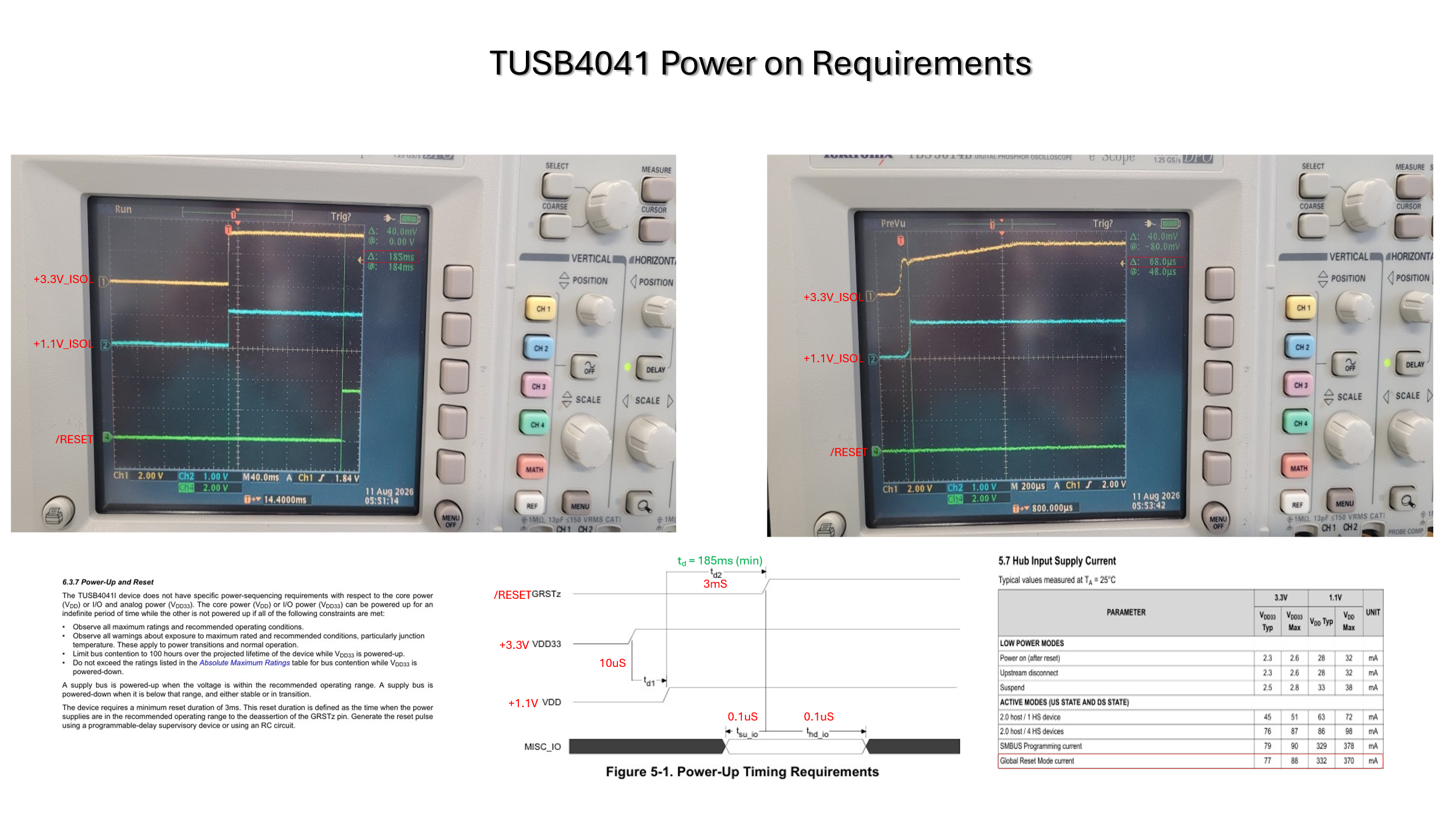
For some reason, this device is not setting the PWRCTL1..4/BATEN1..4 outputs correctly upon reset deassertion. These pins are pulled-up for active high control of power switches. I have a feeling that the device is not initializing properly. The power-on reset is 193mS delayed from the 3.3V power.

The 3.3V ramp up time is 0.9mS while the 1.1V ramp up time is 114uS. The required ramp up time is 0.2mS min on both. I am violating the 1.1V ramp up time. Would this cause the device not to set to default values as shown on some critical inputs?


I requested waveforms VDD, VDD33 and GRSTz, see below. Please let me know which further questions to ask?
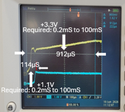
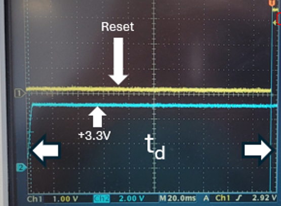
image.png

image.png

3V3 blue waveform is actually Vin of 3V3 LDO LP3961 which is very fast, so I don't see a direct issue here in the ~200ms range.
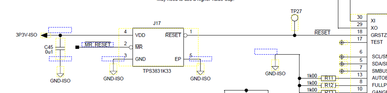
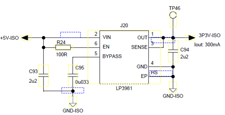
image.png

image.png

Regards,

Frank

  • Hi Frank,

    Some questions:

    For some reason, this device is not setting the PWRCTL1..4/BATEN1..4 outputs correctly upon reset deassertion.

    What is the expected behavior of these pins for the customer? What is the status of PWRCTL_POL? Can the customer share a full pdf schematic?

    Can the customer share a waveform of the PWRCTL signals?

    These pins are pulled-up for active high control of power switches.

    What is the PUP value used here?

    The power-on reset is 193mS delayed from the 3.3V power.

    The 3.3V ramp up time is 0.9mS while the 1.1V ramp up time is 114uS. The required ramp up time is 0.2mS min on both. I am violating the 1.1V ramp up time. Would this cause the device not to set to default values as shown on some critical inputs?

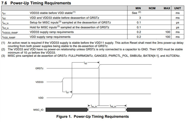
    The power up waveform should look as follows:

    The GRSTZ pin looks to a an actively controlled signal, so VDD does not need to be stable before VCC. 

    We do see that the supply ramps up faster than the minimum spec of 0.2ms. Can the customer share both supplies and reset waveforms on one capture.

    Is the customer using SMBUS mode, I2C mode, or is SMBUSz floating? 

  • Hi Frank,

    Can we keep all communication on E2E? I am not allowed to provide technical support over email.

  • Sure we can keep it over E2E, however who ordered to only communicate over E2E?

    Additional info customer:

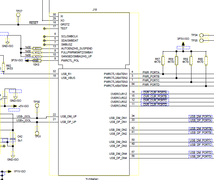
    Here is the partial schematic showing the TUSB4041 configuration.

  • We do see that the supply ramps up faster than the minimum spec of 0.2ms. Can the customer share both supplies and reset waveforms on one capture.

    Is the customer using SMBUS mode, I2C mode, or is SMBUSz floating? 

    Can the customer share a waveform of the PWRCTL signals?

    Can the customer share these waveforms? 

    What does the customer expect to see on the PWRL_CTL pins?

  • Hello,

    Closing thread due to inactivity. If you have any follow-up questions or concerns, feel free to reply.