


Part Number: TUSB422
Hello TI Support Team,
We are preparing a TID/SEE radiation test for the TUSB422 and would like to confirm that our minimal test setup still provides complete functional coverage of the device.
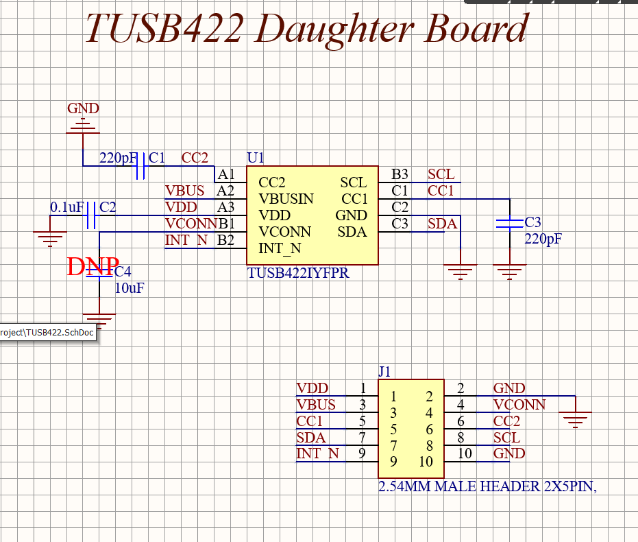
Because of physical constraints inside the beamline, our DUT board is limited to a small 1.5 × 1.5 inch adapter PCB containing only the TUSB422 and its required support capacitors. This adapter plugs into a shielded test‑fixture PCB outside the beam, which holds an Arduino microcontroller and an SMU.
Our planned signal connections are:
• SDA, SCL, and INT_N routed from the DUT to the Arduino
• CC1 and CC2 routed directly from the USB‑C receptacle to the TUSB422 on the adapter board
• VDD monitored by a downstream SMU for latch‑up detection
We are not implementing the full reference design (no high‑speed switching, no DP/DM routing, no VBUS sourcing). Only the CC/I2C pathway is active during radiation exposure.
We would appreciate your guidance on the following points:
-
Radiation Health Monitoring
Is continuously polling the TUSB422’s I2C registers (STATUS, POWER_STATUS, CC_STATUS, device ID, interrupts, etc.) combined with SMU monitoring of VDD current sufficient to detect functional failures during radiation exposure?
Or do certain parts of the analog/PHY block require the full reference circuit to be active in order to validate proper operation? -
PD/BMC Message Handling Over I2C
Our understanding is that the TUSB422’s USB‑PD PHY handles all BMC modulation/demodulation, and the external MCU can fully exchange PD messages through the RX/TX FIFOs over I2C.
Can you confirm that no external PD controller is required for reading/writing PD messages in this test configuration? -
Cable Orientation Detection
In this minimal setup, is it correct that reading CC1_STATE/CC2_STATE and writing PLUG_ORIENTATION over I2C is sufficient for testing orientation‑switch functionality?
Our main question is whether the above minimal CC+I2C wiring is enough to meaningfully verify the TUSB422’s functional health under radiation, or if additional circuitry is required to ensure full coverage.
Thank you for your support and guidance.
