LM62460: Design Review

Part Number: LM62460

Hi,
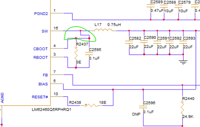
I am planning to use LM62460Q5RPHRQ1 Power regulator to my design. And the design is completed and attached snap for your review.
Please review the circuit and provide your feedback on that.
 Regards,
Vaishnavi

  • Hello Vaishnavi,

    I will get back to you by tomorrow EOD IST.

    Regards,

    Sourish

  • Hello Vaishnavi,

    Here are the comments on the schematic: [50% Derating considered on the output ceramic capacitors, Load=6A Full load, Fsw=1.54MHz as per RT selection]

    1) The control loop is stable as can be seen from the result of the SIMPLIS simulation. [L, Cout are ok]

    2) C2595, the boot capacitor should be connected between CBOOT and SW pin.

    In your current schematic, CBOOT and SW pins are shorted. Kindly place the 0.1uF cap between them.

    3) If the R2438 is 18ohms, kindly increase the resistance to ~100kOhms to limit the sink current through the pin.

    4) Take care of the voltage rating of the capacitors to be at minimum 2 times the voltage they are being operated at.

    5) Take care of the saturation current rating of the inductor according to your load. It should be ~1.5 times the max load of your application for safety margins (I have considered 6A, the max load capacity of the device for the Bode plot).

    6) Consider adding damping on the input filter stage to avoid unwanted overshoots caused by the ferrite bead and the Input filter capacitors coupling. You can calculate the Damping ESR required to be the characteristic impedance of the LC filter i.e; root(L/Cin_ceramics) in your case.

    You can use an electrolytic capacitor with the required ESR for damping the input filter stage.

    Rest of the schematic looks fine.

    Regards,

    Sourish