DS90UB948-Q1: 1080p 60Hz coaxl transmission

Part Number: DS90UB948-Q1
Other Parts Discussed in Thread: DS90UB949-Q1,

Hi All,


I am transmitting a 1080p60Hz video signal using a DS90UB949EVM and DS90UB948EVM configuration.
When using STP, the picture outputs correctly, and the Lock signal is stable.
However, when using coax, the Lock signal toggles between High and Low, and the picture does not output correctly.
The register settings are at their default values ​​for both configurations.

I would like to transmit via coax is there a way to achieve this?


Best Regards,
Ishiwata

  • Hi Ishiwata-san,

    The DS90UB949-Q1 and DS90UB948-Q1 can be configured to operate in coax mode. However, you cannot switch from the default STP mode to coax mode through software configuration alone. Several hardware modifications and device configuration changes are required to properly configure both EVMs for coax operation.

    For the DS90UB949-Q1 EVM:

    1. Remove the common-mode chokes (L10 and L11), then solder 0-Ω resistors across pins 1-2 and 3-4 of both L10 and L11.
    2. Reroute the FPD-Link signals from the HSD connector to the SMA connectors by populating the 0-Ω resistors at R209–R212. This connects the high-speed signals to the SMA connectors.
    3. For the negative (N) signal, terminate connectors J11 and J13 with 50-Ω terminators.
    4. Configure the device for coax mode by setting MODE_SEL1 to Setting #3 using DIP switch S6.

    For the DS90UB948-Q1 EVM:

    1. Modify the hardware similarly to the 949 EVM. Remove L1 and L2. However, I believe pins 1-2 and 3-4 are already shorted together by PCB traces, so additional 0-Ω resistors are not required.
    2. Populate 0-Ω resistors at R37, R38, R63, and R64.
    3. Terminate connectors J9 and J4 with 50-Ω terminators for the negative (N) signal.
    4. Depending on your high-speed back-channel configuration, you may set the 948 back-channel data rate to 5 Mbps by setting DIP switch S2, switch #2.

    After completing these hardware modifications and configuration changes, you should be able to operate the link in coax mode.

    I hope this helps. Please let me know if you have any additional questions.

    Aaron

  • Hi Aaron-san,


    Thank you for your support.
    I configured the system according to your advice, but the lock over coax remained unstable.
    Pressing down with my finger near the AC-coupling capacitors on the DS90UB949's DOUT1+/- lines stabilizes the lock somewhat and slightly reduces the flickering of the EVM's LEDs.
    I also tried changing the AC-coupling capacitors—using 0.1 µF for the DS90UB949 and both 0.1 µF and 0.033 µF for the DS90UB948—but this did not result in any improvement.
    Do you have any recommendations for a solution?


    Best Regards,
    Ishiwata

  • Hi Ishiwata-san,

    What is the length of the cable you are using? Are you using an SMA cable? If possible, could you try using a 1-meter cable instead?

    Also, could you please monitor the LOCK pin on the DS90UB948 and let me know its status?

    Aaron

  • Hi Aaron-san,


    Thank you for your support.
    The cable will be an SMA cable, approximately 20 cm in length.

    We will verify the Lock signal, so please wait a moment.


    I have an additional question.
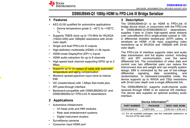
    The datasheet states that "15m communication is possible."
    Could you please clarify the conditions required to achieve this performance?
    (1) Recommended cable specifications and length (including specified components)
    (2) Assumed power supply environment (voltage, allowable ripple, etc.)


    Best Regards,
    Ishiwata

  • Hi Ishiwata-san,

    Yes, we support cable lengths of up to 15 m when using a proper automotive coax cable, such as a 535-3 cable with HSD connectors. However, a 0.2 m cable is actually too short and can degrade the return loss, especially when using SMA cables and connectors.

    There is another configuration that we could try, although it will require a few adapters. I suggest the following connection:

    949 EVM → HSD connector → HSD cable → HSD-to-SMA adapter → short SMA cable → SMA-to-HSD adapter → HSD cable → 948 EVM

    You may terminate the N signal with a 50-Ω terminator on the HSD-to-SMA adapter.

    Please let me know if you have access to these adapters or if you would like to discuss other options.

    Aaron

  • Hi Aaron-san,

    Thank you for your reply.
    We will look for cables and connectors in-house that we can use for verification.

    By the way, are there any points we should be aware of regarding the power supply?


    Also, do you have information on HSD cables that are rated for approximately 500 mating cycles?


    Best Regards,
    Ishiwata

  • Hi Ishiwata-san,

    If you have the schematic available, please share it with me and I would be happy to review it for you. Regarding the EVMs, they should be able to bring up successfully. I can also provide a quick demonstration, possibly early next week.

    Regarding the HSD mating cycles, automotive-grade HSD connectors and cables are typically specified for a relatively low number of mating cycles because they are generally connected only once during vehicle assembly and are not intended for frequent connect/disconnect operations.

    Aaron

  • Hi Aaron-san,

    Thank you for your support.

    We are currently evaluating the EVM, so we do not have a schematic or similar documentation at this stage.
    I asked the question to find out if there are any specific points to watch out for regarding the power supply.
    Am I correct in understanding that the power supply design should be based on the datasheet and the EVM?

    Also, thank you for the information regarding the cables.
    I have a follow-up question: for a 15-meter coaxial transmission, is the recommended setup a "535-3 cable" with an HSD connector?
    I would like to know which specific connectors and cables have a proven track record for 15-meter coaxial transmission.

    Best Regards,
    Ishiwata

  • Hi Ishiwata-san,

    I recommend reviewing the datasheet for the power rail requirements and power sequencing, as it provides the most accurate and up-to-date information. The EVM is intended for evaluation purposes, and some of the power management devices used on the EVM may be older revisions or may have newer alternatives available today.

    The EVM schematic and layout files are available in the user guide. If you need the original source files, I would be happy to provide them. We also have an errata document that describes known device issues along with the recommended workarounds.

    For the HSD connector using the 535-3 cable, the recommended maximum cable length is 15 meters. If it would be helpful, I can perform a quick demonstration in the lab. If you need additional information, such as the cable or connector datasheets, I would be happy to provide those as well.

    Aaron

  • Hi Aaron-san,


    Thank you for your reply.

    Could you please provide datasheets or other information regarding the cables and connectors compatible with coax mode?
    Regarding the demo, does this mean you can provide a video showing 1080p coax transmission?

    Best Regards,
    Ishiwata

  • Hi Ishiwata-san,

    Please give me a few days. I will share the connectors and cables datasheet as well as the demos.

    Aaron