TUSB1310A: Txdetectrx failed at P2 when using 1310A

Part Number: TUSB1310A

Hi Ti exports,

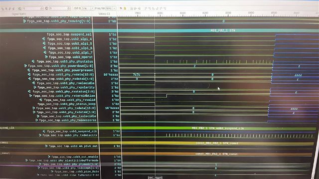
 I am an AE of Siemens EDA and fouce on FPGA prototyping. These days we are debugging TUSB1310A on our platforms. I know this part is NRND but we have sold several extension board with this phy to implement USB3. I encountered the same issue which descripted in TUSB1310A: USB 3.0 Host controller solution - Interface forum - Interface - TI E2E support forums. Txdetectrx failed. I can't see any solution in this jira, so I filed this new one.  This is my first time to debug with this phy. Attached txdetectrx waveform for your reference. If you have any advice, you could contact me via mail zhichao.sheng@siemens.com.Thanks in advance.

image.png

BRs

Zhichao

  • Hi Zhichao:

        Let me review schematic first and get back to you tomorrow.

    Best

    Brian

  • Hi Zhichao:

       From schematic, 

    1:  how do you control USB3_RESETN?

    2: How do you configure strap pins for these signals:

       USB3_PHY_MODE1/0 ( mode)

       RX_ELECIDLE  ( for clock  input)

      OUT_ENABLE ( output enable)

      ULPI_DATA7 ( ISO mode)

    3: What frequency on PCLK?

    Best

    Brian


  • Hi Brian,

    Thanks for your quick response. Attached is the overview of sequence. Let me give some explanations one by one.

    #1 OUT_ENABLE keeps 1 after FPGA programmed, const assign in RTL.

    #2 USB3_PHY_MODE keeps 1 after FPGA programmed, const assign in RTL.

    #3 USB3_RESETN is under manual control. After bitstream download, we manually open the debug window and complete trigger configuration before deasserting the reset. Therefore, the USB3_RESETN signal transitions from 0 to 1 roughly tens of seconds after FPGA power-up. Shown as usb3_mperst in waveform.

    #4 For RX_ELECIDLE, we used it as input signal and probed it. The RX_ELECIDLE is controller by 10k pull-down on PCB, which makes RX_ELECIDLE keeps low during USB3_RESETN is low in waveform.

    #5 For ULPI_DATA4~7, we only probe them on the FPGA side. Their values are entirely determined by the PHY together with pull-up and pull-down resistors. Switch S3 controls a 10k pull-up on ISO_START (switch in direction of pin 1) or a 10k pull-down on ISO_START (switch in direction of pin 3). Now I control the S3 to use 10k pull-down. BTW, although we have pd/pu on these signals in PCB, if I leave ULPI_DATA4~7 floating, the power-on sequence is very strange, phy-status will keeps 1 and never go down. After I pinlock them and probe them in FPGA, power-on sequence is  as expected.

    #6 We previously used the pclk signal for probing. Based on PLL lock status and waveform length measurements, the pclk frequency is 250 MHz.

    Hope to hear from you soon. Thanks in advance.

    BRs

    Zhichao

  • If mperst is is reset signal  then strapping looks ok. But it seems pin J11 (RESETN) and pin J3 (PHY_RESETN) was connected  together in your design. PHY_RESETN should be connected separate from RESETN and should be controlled by a FPGA  IO

    Also have some other questions:

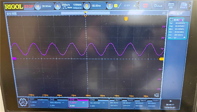
    1; did crystal works fine with 40Mhz?

    2: how about trace length for  PIPE signals ? should be < 2 ins, and how about trace length matching  for PIPE signals?

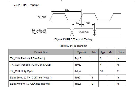
    3: can you look at TX data vs TX_CLK to see if meet timing spec. ?

    4: did you do any timing de-skew


    Best

    Brian

  • Hi Brian,

    #1 PHY_RESETN and RESETN are tied together to a single pin on the PCB directly, and it seems to be impossible for our PCB to rework and implement that. Please help confirm if this separation is mandatory.

    #2 The clock frequency is 40 MHz, please help check if this is OKAY

    #3 For trace length, I will try to double check with RnD, Given our extensive hardware R&D experience, we can first assume there are no errors stemming from such issues.

    #4 No IDELAY is implemented for the PCLK signal after entering the FPGA on customer design.

    #5 TX_CLK is not routed through an ODDR primitive on customer design.

    #6 We will measure the timing of TX data and TX_CLK next week after the customer’s hardware engineer completes the flying wire connections.

     I will bring up a small example to implement the poweron sequence and tedetectrx flow with the correct side-signals by following FPGA timing advice in UG next week. Any update I will sync to you. Thanks.

    BRs

    Zhichao 

  • Crystal output should be around 1.8V, but it was only 1v from your waveform, you may need to add 1 Mohm resistor between XI/XO.

    Best

    Brian

  • Hi Brian,

    No offense intended—thank you for the suggestion. But according to Table 3-5 of the TUSB1310A datasheet, the 1.8 V specification appears to refer to an external clock applied to XI. When a passive crystal is connected between XI and XO, these pins operate as analog oscillator nodes, so the XO waveform is not necessarily expected to reach a 1.8 V logic level.

    In our measurement, the crystal oscillates steadily at 40 MHz, and the PHY generates a locked 250 MHz PCLK. These results suggest that the oscillator and internal PLL are operating correctly.

    Therefore, it may be helpful to confirm whether the 1 MΩ resistor is specifically recommended for this device. TI’s typical crystal connection does not show one, although we may add one in the further debug.

    A bad news is that, due to customer new project bringup, HW team may not support us to debug this issue. I have tried to use a small example to test on this phy with TXCLK and PCLK phase-shifted, and the issue is the same. Txdetectrx failed. Attached the entire sequence RTL for your reference.

    //=============================================================================
    //  Module      : usb3_tusb1310_ctrl
    //  Description : FPGA controller for TI TUSB1310A USB 3.0 SuperSpeed PHY
    //                Power-up → Rx.Detect (retry if not present) → P0 → LFPS.
    //                PIPE I/O registers forced into IOB (ILOGIC/OLOGIC).
    //
    //  PCLK = 250 MHz, period = 4 ns
    //  Reference   : TUSB1310 Data Manual (ZHCS454E)
    //=============================================================================
    
    module usb3_tusb1310_ctrl #(
        parameter SYS_CLK_FREQ_HZ    = 100_000_000,
        parameter RESET_HOLD_CYCLES  = 200,
        parameter PLL_LOCK_TIMEOUT   = 40000,
        parameter PCLK_STABLE_COUNT  = 16
    ) (
        input  wire        sys_clk,
        input  wire        sys_rst_n,
    
        // PIPE TX — driven by OLOGIC registers
        output wire        tx_clk,
        output wire [15:0] tx_data,
        output wire [1:0]  tx_datak,
        output wire        tx_detrx_lpbk,
        output wire        tx_elecidle,
        output wire        tx_oneszeros,
        output wire [1:0]  tx_deemph,
        output wire [2:0]  tx_margin,
        output wire        tx_swing,
        output wire        rx_polarity,
        output wire        rx_termination,
        output wire [1:0]  power_down,
        output wire        rate,
        output wire        elas_buf_mode,
        output wire        phy_reset_n,
    
        // PIPE RX — captured by ILOGIC registers
        input  wire        pclk,
        input  wire [15:0] rx_data,
        input  wire [1:0]  rx_datak,
        input  wire        rx_valid,
        input  wire [2:0]  rx_status,
        input  wire        rx_elecidle,
        input  wire        phy_status,
    
        // Global (sys_clk domain)
        output reg         reset_n,
        output reg         out_enable,
    
        // Status
        output wire        phy_ready,
        output wire        rx_detect_done,
        output wire        rx_detect_result,
        output wire [3:0]  fsm_state
    );
    wire pipe_busy;
    wire pclk_domain_rst_n;
    
        //=========================================================================
        // Local Parameters
        //=========================================================================
        localparam P0 = 2'b00;
        localparam P2 = 2'b10;
        localparam RX_DET_NOT_PRESENT = 3'b000;
        localparam RX_DET_PRESENT     = 3'b011;
    
        //=========================================================================
        // PIPE RX IOB Registers (ILOGIC) — 1st stage after input pad
        //=========================================================================
        (* IOB = "TRUE" *) reg [15:0] rx_data_r;
        (* IOB = "TRUE" *) reg [1:0]  rx_datak_r;
        (* IOB = "TRUE" *) reg        rx_valid_r;
        (* IOB = "TRUE" *) reg [2:0]  rx_status_r;
        (* IOB = "TRUE" *) reg        rx_elecidle_r;
        (* IOB = "TRUE" *) reg        phy_status_r;
    
        always @(posedge pclk) begin
            rx_data_r      <= rx_data;
            rx_datak_r     <= rx_datak;
            rx_valid_r     <= rx_valid;
            rx_status_r    <= rx_status;
            rx_elecidle_r  <= rx_elecidle;
            phy_status_r   <= phy_status;
        end
    
        //=========================================================================
        // PIPE TX IOB Registers (OLOGIC) — last stage before output pad
        //=========================================================================
        (* IOB = "TRUE" *) reg [15:0] tx_data_o;
        (* IOB = "TRUE" *) reg [1:0]  tx_datak_o;
        (* IOB = "TRUE" *) reg        tx_detrx_lpbk_o;
        (* IOB = "TRUE" *) reg        tx_elecidle_o;
        (* IOB = "TRUE" *) reg        tx_oneszeros_o;
        (* IOB = "TRUE" *) reg [1:0]  tx_deemph_o;
        (* IOB = "TRUE" *) reg [2:0]  tx_margin_o;
        (* IOB = "TRUE" *) reg        tx_swing_o;
        (* IOB = "TRUE" *) reg        rx_polarity_o;
        (* IOB = "TRUE" *) reg        rx_termination_o;
        (* IOB = "TRUE" *) reg [1:0]  power_down_o;
        (* IOB = "TRUE" *) reg        rate_o;
        (* IOB = "TRUE" *) reg        elas_buf_mode_o;
        (* IOB = "TRUE" *) reg        phy_reset_n_o;
    
        // Connect OLOGIC registers to output ports
        assign tx_data        = tx_data_o;
        assign tx_datak       = tx_datak_o;
        assign tx_detrx_lpbk  = tx_detrx_lpbk_o;
        assign tx_elecidle    = tx_elecidle_o;
        assign tx_oneszeros   = tx_oneszeros_o;
        assign tx_deemph      = tx_deemph_o;
        assign tx_margin      = tx_margin_o;
        assign tx_swing       = tx_swing_o;
        assign rx_polarity    = rx_polarity_o;
        assign rx_termination = rx_termination_o;
        assign power_down     = power_down_o;
        assign rate           = rate_o;
        assign elas_buf_mode  = elas_buf_mode_o;
        assign phy_reset_n    = phy_reset_n_o;
      ODDRE1 #(
          .IS_C_INVERTED(1'b0),           // Optional inversion for C
          .IS_D1_INVERTED(1'b0),          // Unsupported, do not use
          .IS_D2_INVERTED(1'b0),          // Unsupported, do not use
          .SIM_DEVICE("ULTRASCALE_PLUS"), // Set the device version for simulation functionality (ULTRASCALE,
                                          // ULTRASCALE_PLUS, ULTRASCALE_PLUS_ES1, ULTRASCALE_PLUS_ES2)
          .SRVAL(1'b0)                    // Initializes the ODDRE1 Flip-Flops to the specified value (1'b0, 1'b1)
       )
       u_txclk_oddr (
          .Q(tx_clk),   // 1-bit output: Data output to IOB
          .C(pclk),   // 1-bit input: High-speed clock input
          .D1(1'b0), // 1-bit input: Parallel data input 1
          .D2(1'b1), // 1-bit input: Parallel data input 2
          .SR(1'b0)  // 1-bit input: Active-High Async Reset
       );
    
    
        //=========================================================================
        // sys_clk Domain — Power-Up FSM
        //=========================================================================
        localparam SYS_INIT          = 4'd0;
        localparam SYS_RESET_HOLD    = 4'd1;
        localparam SYS_WAIT_PCLK     = 4'd2;
        localparam SYS_WAIT_PHY_RDY  = 4'd3;
        localparam SYS_DONE          = 4'd4;
    
        reg  [3:0]  sys_state, sys_state_next;
        reg  [15:0] sys_counter;
        reg         sys_phy_ready;
        reg         sys_pipe_start;
        reg  [2:0]  phy_status_sync;
    
        reg  pclk_alive_toggle, pclk_alive_d1, pclk_alive_d2, pclk_alive_stuck;
    
        initial begin
            pclk_alive_d1    = 1'b0;
            pclk_alive_d2    = 1'b0;
            pclk_alive_stuck = 1'b1;
            phy_status_sync  = 3'd0;
        end
    
        always @(posedge sys_clk or negedge sys_rst_n) begin
            if (!sys_rst_n) begin
                pclk_alive_d1    <= 1'b0;
                pclk_alive_d2    <= 1'b0;
                pclk_alive_stuck <= 1'b1;
            end else begin
                pclk_alive_d1    <= pclk_alive_toggle;
                pclk_alive_d2    <= pclk_alive_d1;
                pclk_alive_stuck <= (pclk_alive_d2 == pclk_alive_d1);
            end
        end
    
        // sys_clk FSM
        always @(posedge sys_clk or negedge sys_rst_n) begin
            if (!sys_rst_n) begin
                sys_state      <= SYS_INIT;
                sys_counter    <= 16'd0;
                reset_n        <= 1'b0;
                out_enable     <= 1'b1;
                sys_pipe_start <= 1'b0;
                sys_phy_ready  <= 1'b0;
            end else begin
                sys_state <= sys_state_next;
                case (sys_state)
                    SYS_INIT: begin
                        reset_n <= 1'b0; out_enable <= 1'b1; sys_counter <= 16'd0;
                    end
                    SYS_RESET_HOLD: begin
                        reset_n <= 1'b0; out_enable <= 1'b1;
                        sys_counter <= sys_counter + 16'd1;
                    end
                    SYS_WAIT_PCLK: begin
                        reset_n <= 1'b1; out_enable <= 1'b1;
                        sys_counter <= sys_counter + 16'd1;
                    end
                    SYS_WAIT_PHY_RDY: begin
                        reset_n <= 1'b1; out_enable <= 1'b1;
                        sys_counter <= sys_counter + 16'd1;
                        if (phy_status_sync[2] == 1'b0)
                            sys_pipe_start <= 1'b1;
                    end
                    SYS_DONE: begin
                        reset_n <= 1'b1; out_enable <= 1'b1;
                        if (!pipe_busy) sys_pipe_start <= 1'b0;
                        sys_phy_ready <= 1'b1;
                    end
                    default: begin
                        reset_n <= 1'b0; out_enable <= 1'b1;
                    end
                endcase
            end
        end
    
        always @(*) begin
            sys_state_next = sys_state;
            case (sys_state)
                SYS_INIT:       sys_state_next = SYS_RESET_HOLD;
                SYS_RESET_HOLD: if (sys_counter >= RESET_HOLD_CYCLES) sys_state_next = SYS_WAIT_PCLK;
                SYS_WAIT_PCLK:  if (!pclk_alive_stuck && sys_counter >= PLL_LOCK_TIMEOUT) sys_state_next = SYS_WAIT_PHY_RDY;
                SYS_WAIT_PHY_RDY: if (phy_status_sync[2] == 1'b0) sys_state_next = SYS_DONE;
                SYS_DONE:       sys_state_next = SYS_DONE;
                default:        sys_state_next = SYS_INIT;
            endcase
        end
    
        always @(posedge sys_clk or negedge sys_rst_n) begin
            if (!sys_rst_n) phy_status_sync <= 3'd0;
            else phy_status_sync <= {phy_status_sync[1:0], phy_status_r};
        end
    
        //=========================================================================
        // pclk Domain — PIPE FSM (250 MHz, open-loop timing)
        //
        // Sequence:
        //   0. WAIT_2MS:        wait 2.117249ms, power_down=P2, tx_detrx_lpbk=0, rx_termination=0
        //   1. DETECT_START:    tx_detrx_lpbk=1, wait 20ns
        //   2. DETECT_TERM:     rx_termination=1, wait phy_status_r posedge
        //   3. DETECT_CHECK:    tx_detrx_lpbk=0, check rx_status_r
        //         rx_status_r==0 → DETECT_RETRY → back to 1
        //         rx_status_r==3 → P0_DELAY
        //   4. P0_DELAY:        wait 42ns, power_down=P0
        //   5. P0_WAIT:         wait 400µs
        //   6. LFPS:            tx_detrx_lpbk 1µs H / 9µs L, loop forever
        //=========================================================================
        localparam PIPE_WAIT_2MS      = 4'd0;
        localparam PIPE_DETECT_START  = 4'd1;
        localparam PIPE_DETECT_TERM   = 4'd2;
        localparam PIPE_DETECT_CHECK  = 4'd3;
        localparam PIPE_DETECT_RETRY  = 4'd4;
        localparam PIPE_P0_DELAY      = 4'd5;
        localparam PIPE_P0_WAIT       = 4'd6;
        localparam PIPE_LFPS          = 4'd7;
    
        // Timing (PCLK = 250 MHz, period = 4 ns)
        localparam WAIT_2MS_CYCLES    = 20'd529312;  // 2.117249 ms / 4 ns
        localparam DETECT_20NS_CYCLES = 4'd5;        // 20 ns / 4 ns
        localparam P0_DELAY_CYCLES    = 4'd11;       // 42 ns → ~44 ns
        localparam P0_WAIT_CYCLES     = 20'd100000;  // 400 µs / 4 ns
        localparam LFPS_HIGH_CYCLES   = 12'd250;     // 1 µs / 4 ns
        localparam LFPS_LOW_CYCLES    = 12'd2250;    // 9 µs / 4 ns
        localparam LFPS_PERIOD        = 12'd2500;    // 10 µs / 4 ns
    
        reg [3:0]  pipe_state, pipe_state_next;
        reg        pipe_phy_status_r_d;
        reg        pipe_rx_detect_done;
        reg        pipe_rx_detect_result;
        reg        pipe_busy_r;
        reg [19:0] pipe_wait_counter;
        reg [11:0] lfps_counter;
    
        reg [2:0]  sys_pipe_start_sync;
        initial sys_pipe_start_sync = 3'd0;
        wire pipe_start_req;
        always @(posedge pclk) sys_pipe_start_sync <= {sys_pipe_start_sync[1:0], sys_pipe_start};
        assign pipe_start_req = sys_pipe_start_sync[2] && !sys_pipe_start_sync[1];
    
        initial begin
            pipe_state            = PIPE_WAIT_2MS;
            tx_detrx_lpbk_o       = 1'b0;
            tx_elecidle_o         = 1'b1;
            tx_data_o             = 16'd0;
            tx_datak_o            = 2'b00;
            tx_oneszeros_o        = 1'b0;
            rx_termination_o      = 1'b0;
            power_down_o          = P2;
            pipe_rx_detect_done   = 1'b0;
            pipe_rx_detect_result = 1'b0;
            pipe_busy_r           = 1'b0;
            pipe_wait_counter     = 20'd0;
            lfps_counter          = 12'd0;
        end
    
        //-----------------------------------------------------------------
        // Main PIPE FSM — drives OLOGIC registers
        //-----------------------------------------------------------------
        always @(posedge pclk) begin
            if (!pclk_domain_rst_n) begin
                pipe_state            <= PIPE_WAIT_2MS;
                tx_detrx_lpbk_o       <= 1'b0;
                tx_elecidle_o         <= 1'b1;
                tx_data_o             <= 16'd0;
                tx_datak_o            <= 2'b00;
                tx_oneszeros_o        <= 1'b0;
                rx_termination_o      <= 1'b0;
                power_down_o          <= P2;
                pipe_rx_detect_done   <= 1'b0;
                pipe_rx_detect_result <= 1'b0;
                pipe_busy_r           <= 1'b0;
                lfps_counter          <= 12'd0;
            end else begin
                pipe_state  <= pipe_state_next;
                pipe_busy_r <= 1'b1;
    
                case (pipe_state)
                    PIPE_WAIT_2MS: begin
                        tx_detrx_lpbk_o  <= 1'b0; tx_elecidle_o <= 1'b1;
                        rx_termination_o <= 1'b0; power_down_o  <= P2;
                        tx_data_o <= 16'd0; tx_datak_o <= 2'b00; tx_oneszeros_o <= 1'b0;
                        lfps_counter <= 12'd0;
                    end
                    PIPE_DETECT_START: begin
                        tx_detrx_lpbk_o  <= 1'b1; tx_elecidle_o <= 1'b1;
                        rx_termination_o <= 1'b0; power_down_o  <= P2;
                        tx_data_o <= 16'd0; tx_datak_o <= 2'b00; tx_oneszeros_o <= 1'b0;
                        lfps_counter <= 12'd0;
                    end
                    PIPE_DETECT_TERM: begin
                        tx_detrx_lpbk_o  <= 1'b1; tx_elecidle_o <= 1'b1;
                        rx_termination_o <= 1'b1; power_down_o  <= P2;
                        tx_data_o <= 16'd0; tx_datak_o <= 2'b00; tx_oneszeros_o <= 1'b0;
                        lfps_counter <= 12'd0;
                    end
                    PIPE_DETECT_CHECK: begin
                        tx_detrx_lpbk_o  <= 1'b0; tx_elecidle_o <= 1'b1;
                        rx_termination_o <= 1'b1; power_down_o  <= P2;
                        tx_data_o <= 16'd0; tx_datak_o <= 2'b00; tx_oneszeros_o <= 1'b0;
                        pipe_rx_detect_result <= (rx_status_r == RX_DET_PRESENT);
                        lfps_counter <= 12'd0;
                    end
                    PIPE_DETECT_RETRY: begin
                        tx_detrx_lpbk_o  <= 1'b0; tx_elecidle_o <= 1'b1;
                        rx_termination_o <= 1'b1; power_down_o  <= P2;
                        tx_data_o <= 16'd0; tx_datak_o <= 2'b00; tx_oneszeros_o <= 1'b0;
                        lfps_counter <= 12'd0;
                    end
                    PIPE_P0_DELAY: begin
                        tx_detrx_lpbk_o  <= 1'b0; tx_elecidle_o <= 1'b1;
                        rx_termination_o <= 1'b1; power_down_o  <= P0;
                        tx_data_o <= 16'd0; tx_datak_o <= 2'b00; tx_oneszeros_o <= 1'b0;
                        lfps_counter <= 12'd0;
                    end
                    PIPE_P0_WAIT: begin
                        tx_detrx_lpbk_o  <= 1'b0; tx_elecidle_o <= 1'b1;
                        rx_termination_o <= 1'b1; power_down_o  <= P0;
                        tx_data_o <= 16'd0; tx_datak_o <= 2'b00; tx_oneszeros_o <= 1'b0;
                        lfps_counter <= 12'd0;
                    end
                    PIPE_LFPS: begin
                        tx_elecidle_o    <= 1'b1;
                        rx_termination_o <= 1'b1; power_down_o  <= P0;
                        tx_data_o <= 16'd0; tx_datak_o <= 2'b00; tx_oneszeros_o <= 1'b0;
                        if (lfps_counter < LFPS_HIGH_CYCLES)
                            tx_detrx_lpbk_o <= 1'b1;
                        else
                            tx_detrx_lpbk_o <= 1'b0;
                        if (lfps_counter >= LFPS_PERIOD - 1)
                            lfps_counter <= 12'd0;
                        else
                            lfps_counter <= lfps_counter + 12'd1;
                    end
                    default: begin
                        tx_detrx_lpbk_o <= 1'b0; tx_elecidle_o <= 1'b1;
                        rx_termination_o <= 1'b0; power_down_o <= P2;
                        tx_data_o <= 16'd0; tx_datak_o <= 2'b00; tx_oneszeros_o <= 1'b0;
                        pipe_busy_r <= 1'b0; lfps_counter <= 12'd0;
                    end
                endcase
            end
        end
    
        //-----------------------------------------------------------------
        // Wait counter (shared)
        //-----------------------------------------------------------------
        always @(posedge pclk) begin
            if (!pclk_domain_rst_n)
                pipe_wait_counter <= 20'd0;
            else if (pipe_state != pipe_state_next)
                pipe_wait_counter <= 20'd0;
            else if (pipe_state == PIPE_WAIT_2MS ||
                     pipe_state == PIPE_DETECT_START ||
                     pipe_state == PIPE_DETECT_RETRY ||
                     pipe_state == PIPE_P0_DELAY ||
                     pipe_state == PIPE_P0_WAIT)
                pipe_wait_counter <= pipe_wait_counter + 20'd1;
        end
    
        //-----------------------------------------------------------------
        // PHY_STATUS posedge detect (uses registered phy_status_r)
        //-----------------------------------------------------------------
        always @(posedge pclk) begin
            if (!pclk_domain_rst_n) pipe_phy_status_r_d <= 1'b0;
            else pipe_phy_status_r_d <= phy_status_r;
        end
        wire pipe_phy_status_r_posedge = phy_status_r && !pipe_phy_status_r_d;
    
        //-----------------------------------------------------------------
        // Next-state logic
        //-----------------------------------------------------------------
        always @(*) begin
            pipe_state_next = pipe_state;
            case (pipe_state)
                PIPE_WAIT_2MS:      if (pipe_wait_counter >= WAIT_2MS_CYCLES) pipe_state_next = PIPE_DETECT_START;
                PIPE_DETECT_START:  if (pipe_wait_counter >= DETECT_20NS_CYCLES) pipe_state_next = PIPE_DETECT_TERM;
                PIPE_DETECT_TERM:   if (pipe_phy_status_r_posedge) pipe_state_next = PIPE_DETECT_CHECK;
                PIPE_DETECT_CHECK:
                    if (rx_status_r == RX_DET_NOT_PRESENT)      pipe_state_next = PIPE_DETECT_RETRY;
                    else if (rx_status_r == RX_DET_PRESENT)     pipe_state_next = PIPE_P0_DELAY;
                PIPE_DETECT_RETRY:  if (pipe_wait_counter >= 4'd4) pipe_state_next = PIPE_DETECT_START;
                PIPE_P0_DELAY:      if (pipe_wait_counter >= P0_DELAY_CYCLES) pipe_state_next = PIPE_P0_WAIT;
                PIPE_P0_WAIT:       if (pipe_wait_counter >= P0_WAIT_CYCLES) pipe_state_next = PIPE_LFPS;
                PIPE_LFPS:          pipe_state_next = PIPE_LFPS;
                default:            pipe_state_next = PIPE_WAIT_2MS;
            endcase
        end
    
        //=========================================================================
        // Static TX Signal Assignments (PCLK domain)
        //=========================================================================
        initial begin
            tx_deemph_o = 2'b01; tx_margin_o = 3'b000; tx_swing_o = 1'b0;
            rx_polarity_o = 1'b0; rate_o = 1'b1; elas_buf_mode_o = 1'b0; phy_reset_n_o = 1'b1;
        end
        always @(posedge pclk) begin
            if (!pclk_domain_rst_n) begin
                tx_deemph_o <= 2'b01; tx_margin_o <= 3'b000; tx_swing_o <= 1'b0;
                rx_polarity_o <= 1'b0; rate_o <= 1'b1; elas_buf_mode_o <= 1'b0; phy_reset_n_o <= 1'b1;
            end
        end
    
        //=========================================================================
        // PCLK Alive Toggle + pclk_domain_rst_n
        //=========================================================================
        reg [3:0] pclk_toggle_counter;
        reg [1:0] pclk_rst_sync;
        initial begin
            pclk_toggle_counter = 4'd0; pclk_alive_toggle = 1'b0; pclk_rst_sync = 2'd0;
        end
        always @(posedge pclk or negedge reset_n) begin
            if (!reset_n) pclk_rst_sync <= 2'd0;
            else          pclk_rst_sync <= {pclk_rst_sync[0], 1'b1};
        end
        assign pclk_domain_rst_n = pclk_rst_sync[1];
    
        always @(posedge pclk) begin
            if (!pclk_domain_rst_n) begin
                pclk_toggle_counter <= 4'd0; pclk_alive_toggle <= 1'b0;
            end else begin
                pclk_toggle_counter <= pclk_toggle_counter + 4'd1;
                if (pclk_toggle_counter == 4'd0) pclk_alive_toggle <= ~pclk_alive_toggle;
            end
        end
    
        //=========================================================================
        // CDC: pipe_busy → sys_clk
        //=========================================================================
        reg [2:0] pipe_busy_sync;
        always @(posedge sys_clk or negedge sys_rst_n) begin
            if (!sys_rst_n) pipe_busy_sync <= 3'd0;
            else pipe_busy_sync <= {pipe_busy_sync[1:0], pipe_busy_r};
        end
        assign pipe_busy = pipe_busy_sync[2];
    
        //=========================================================================
        // Outputs
        //=========================================================================
        assign phy_ready        = sys_phy_ready;
        assign rx_detect_done   = pipe_rx_detect_done;
        assign rx_detect_result = pipe_rx_detect_result;
        assign fsm_state        = sys_phy_ready ? pipe_state : {1'b0, sys_state[2:0]};
    
    endmodule
    
    
    //=============================================================================
    //  usb3_tusb1310_top — Top-level wrapper
    //=============================================================================
    module usb3_tusb1310_top #(parameter SYS_CLK_FREQ_HZ = 100_000_000) (
        input  wire        sys_clk_100m, sys_rst_n,
        output wire        tusb_tx_clk,
        output wire        tusb_tx_data_0,
        output wire        tusb_tx_data_1,
        output wire        tusb_tx_data_2,
        output wire        tusb_tx_data_3,
        output wire        tusb_tx_data_4,
        output wire        tusb_tx_data_5,
        output wire        tusb_tx_data_6,
        output wire        tusb_tx_data_7,
        output wire        tusb_tx_data_8,
        output wire        tusb_tx_data_9,
        output wire        tusb_tx_data_10,
        output wire        tusb_tx_data_11,
        output wire        tusb_tx_data_12,
        output wire        tusb_tx_data_13,
        output wire        tusb_tx_data_14,
        output wire        tusb_tx_data_15,
        output wire        tusb_tx_datak_0,
        output wire        tusb_tx_datak_1,
        output wire        tusb_tx_detrx_lpbk,
        output wire        tusb_tx_elecidle,
        output wire        tusb_tx_oneszeros,
        output wire        tusb_tx_deemph_0,
        output wire        tusb_tx_deemph_1,
        output wire        tusb_tx_margin_0,
        output wire        tusb_tx_margin_1,
        output wire        tusb_tx_margin_2,
        output wire        tusb_tx_swing,
        output wire        tusb_rx_polarity,
        output wire        tusb_rx_termination,
        output wire        tusb_power_down_0,
        output wire        tusb_power_down_1,
        output wire        tusb_rate,
        output wire        tusb_elas_buf_mode,
        output wire        tusb_phy_reset_n,
    
        // TUSB1310 PIPE RX Interface (external pins — single-bit only for PAD)
        input  wire        tusb_pclk_in,
        input  wire        tusb_rx_data_0,
        input  wire        tusb_rx_data_1,
        input  wire        tusb_rx_data_2,
        input  wire        tusb_rx_data_3,
        input  wire        tusb_rx_data_4,
        input  wire        tusb_rx_data_5,
        input  wire        tusb_rx_data_6,
        input  wire        tusb_rx_data_7,
        input  wire        tusb_rx_data_8,
        input  wire        tusb_rx_data_9,
        input  wire        tusb_rx_data_10,
        input  wire        tusb_rx_data_11,
        input  wire        tusb_rx_data_12,
        input  wire        tusb_rx_data_13,
        input  wire        tusb_rx_data_14,
        input  wire        tusb_rx_data_15,
        input  wire        tusb_rx_datak_0,
        input  wire        tusb_rx_datak_1,
        input  wire        tusb_rx_valid,
        input  wire        tusb_rx_status_0,
        input  wire        tusb_rx_status_1,
        input  wire        tusb_rx_status_2,
        input  wire        tusb_rx_elecidle,
        input  wire        tusb_phy_status,
        input  wire        tusb_pwrpresent,
        input wire		ulpi_4,
        input wire		ulpi_5,
        input wire		ulpi_6,
        input wire		ulpi_7,
        input dbg_clk,
        // Global Control
        output wire        tusb_reset_n,
        output wire        tusb_en_P5V0_out,
        output wire	       tusb_phy_mode_0,
        output wire	       tusb_phy_mode_1,
        output wire        tusb_out_enable
    
    );
        wire        led_phy_ready;
        wire        led_rx_detect_done;
        wire        led_rx_detect_result;
    assign tusb_en_P5V0_out =1;
    assign tusb_phy_mode_0 =1;
    assign tusb_phy_mode_1 =0;
        //-------------------------------------------------------------------------
        // Bus Packing / Unpacking (single-bit PAD ports ↔ multi-bit internal buses)
        //-------------------------------------------------------------------------
        wire [15:0] tusb_tx_data  ;
        	assign {tusb_tx_data_15, tusb_tx_data_14, tusb_tx_data_13, tusb_tx_data_12,
                                      tusb_tx_data_11, tusb_tx_data_10, tusb_tx_data_9,  tusb_tx_data_8,
                                      tusb_tx_data_7,  tusb_tx_data_6,  tusb_tx_data_5,  tusb_tx_data_4,
                                      tusb_tx_data_3,  tusb_tx_data_2,  tusb_tx_data_1,  tusb_tx_data_0} = tusb_tx_data;
        wire [1:0]  tusb_tx_datak ; 
       assign {tusb_tx_datak_1, tusb_tx_datak_0} = tusb_tx_datak;
        wire [1:0]  tusb_tx_deemph; 
      assign {tusb_tx_deemph_1, tusb_tx_deemph_0} = tusb_tx_deemph;
        wire [2:0]  tusb_tx_margin;  
        assign {tusb_tx_margin_2, tusb_tx_margin_1, tusb_tx_margin_0}= {1'b0,~tusb_reset_n,~tusb_reset_n};
        wire [1:0]  tusb_power_down  ;
        assign  {tusb_power_down_1, tusb_power_down_0} = tusb_power_down;
    
        wire [15:0] tusb_rx_data    = {tusb_rx_data_15, tusb_rx_data_14, tusb_rx_data_13, tusb_rx_data_12,
                                        tusb_rx_data_11, tusb_rx_data_10, tusb_rx_data_9,  tusb_rx_data_8,
                                        tusb_rx_data_7,  tusb_rx_data_6,  tusb_rx_data_5,  tusb_rx_data_4,
                                        tusb_rx_data_3,  tusb_rx_data_2,  tusb_rx_data_1,  tusb_rx_data_0};
        wire [1:0]  tusb_rx_datak   = {tusb_rx_datak_1, tusb_rx_datak_0};
        wire [2:0]  tusb_rx_status  = {tusb_rx_status_2, tusb_rx_status_1, tusb_rx_status_0};
    
        wire [3:0]  led_fsm_state;
        assign led_fsm_state_0 = led_fsm_state[0];
        assign led_fsm_state_1 = led_fsm_state[1];
        assign led_fsm_state_2 = led_fsm_state[2];
        assign led_fsm_state_3 = led_fsm_state[3];
      clk_wiz_0 u_mmcm
       (
        // Clock out ports
        .clk_out1(tusb_pclk),     // output clk_out1
       // Clock in ports
        .clk_in1(tusb_pclk_in)      // input clk_in1
    );
    
        usb3_tusb1310_ctrl #(
            .SYS_CLK_FREQ_HZ(SYS_CLK_FREQ_HZ), .RESET_HOLD_CYCLES(200),
            .PLL_LOCK_TIMEOUT(40000), .PCLK_STABLE_COUNT(16)
        ) u_ctrl (
            .sys_clk(sys_clk_100m), .sys_rst_n(sys_rst_n),
            .tx_clk(tusb_tx_clk), .tx_data(tusb_tx_data), .tx_datak(tusb_tx_datak),
            .tx_detrx_lpbk(tusb_tx_detrx_lpbk), .tx_elecidle(tusb_tx_elecidle),
            .tx_oneszeros(tusb_tx_oneszeros), .tx_deemph(tusb_tx_deemph),
            //.tx_margin(tusb_tx_margin), 
    	.tx_swing(tusb_tx_swing),
            .rx_polarity(tusb_rx_polarity), .rx_termination(tusb_rx_termination),
            .power_down(tusb_power_down), .rate(tusb_rate),
            .elas_buf_mode(tusb_elas_buf_mode), .phy_reset_n(tusb_phy_reset_n),
            .pclk(tusb_pclk), .rx_data(tusb_rx_data), .rx_datak(tusb_rx_datak),
            .rx_valid(tusb_rx_valid), .rx_status(tusb_rx_status),
            .rx_elecidle(tusb_rx_elecidle), .phy_status(tusb_phy_status),
            .reset_n(tusb_reset_n), .out_enable(tusb_out_enable),
            .phy_ready(led_phy_ready), .rx_detect_done(led_rx_detect_done),
            .rx_detect_result(led_rx_detect_result), .fsm_state(led_fsm_state)
        );
    endmodule
    

    Related to RESETN and PHY_RESET_N, https://github.com/mossmann/daisho/tree/1d2f5e1cb16a9a724f957cc6c99e63b601e5cac0 shows a example to use altera FPGA to control TUSB1310A. RESETN and PHY_RESET_N are almost the same one in the design, because the phy_pwrpresent should be 1 after FPGA power on. So I think the RESET issue may not the root cause of this issue.

    At this point, I seem to have reached a bit of a roadblock and am not quite sure what to investigate next. No offense intended, and I really appreciate your suggestion. Do you have any other recommendations or areas you think would be worth checking?

    BRs

    Zhichao

  • Hi Zhichao:

      If PCLK is stable, then crystal should be fine without 1 Mohm resistor..

     Did you get PIPE trace length information? Did you get chance to measure timing between data and TCLK/PCLK? It's  critical to do timing deskew for PIPE.

    Regards

    Brian