This thread has been locked.

If you have a related question, please click the "Ask a related question" button in the top right corner. The newly created question will be automatically linked to this question.

DP83869HM: VDDIO possible rise time violation

Part Number: DP83869HM
Other Parts Discussed in Thread: DP83869

I am having an issue where around 1/600 times that I start up my PCBA, the DP83869 doesn't come up correctly and start talking to my MCU. I'm concerned that this could be related to the rise time of the VDDIO rail, because it doesn't have a consistent linear trend that fits the >500us rise time standard. 
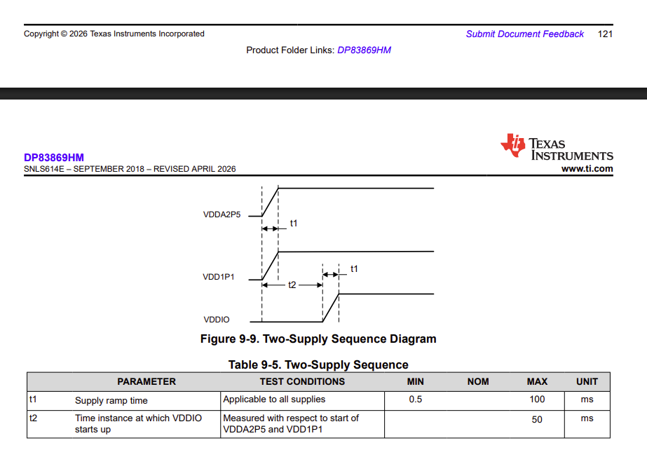
image.png

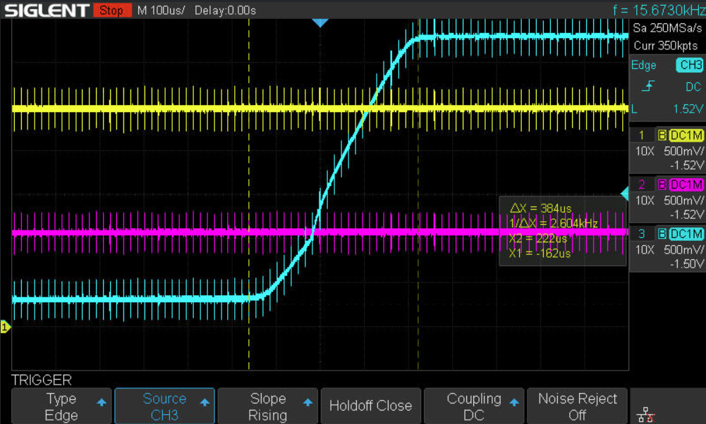
In the scope capture from my PCBA below, yellow is 2V5, pink is 1V1, and blue is 3V3 (VDDIO). You can see that 2V5 and 1V1 rise smoothly over the course of a few ms, but the 3V3 (VDDIO) rises slowly at first and then jumps from ~300mV to 3.3V in under 500us. 
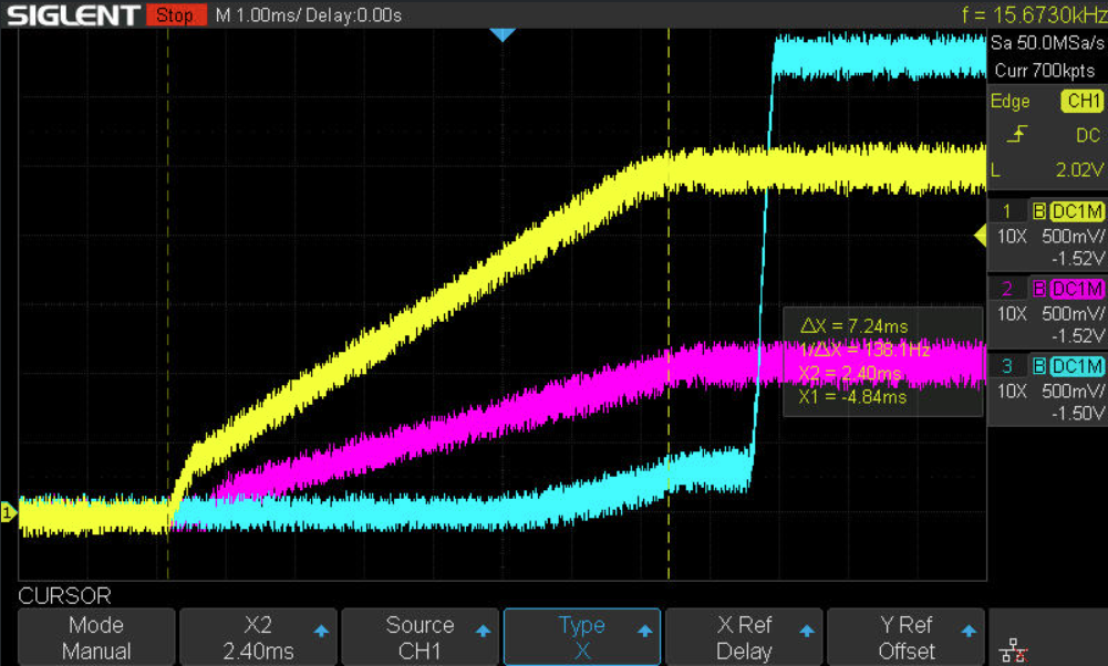
image.png

image.png

A couple questions: 

  • What drives the 500us minimum ramp requirement for the power rails?
  • Does this power up timing sequencing seem like a potential issue that could be the root cause of the occasional startup failures we see? 
  • Hi Suzanne,

    I will look into this and will get back to you as soon as possible.

    Best regards,

    Greg

  • Hi Suzanne,

    The recommendation of at least a 500us ramp time for VDDIO is made to ensure all straps are sampled correctly on startup. What is the current ramp time of the 3.3V rail?

    Best regards,

    Greg

  • Hi Gregory, 

    Thanks for following up. The blue lines in the scope shots I attached above are the 3.3V rail.

    * If you measure from where the blue starts ramping slowly, you get a 3.72ms ramp time.

    * If you measure just the time where the slope is more steep, you get 350us.

    It's not clear to me which of these measurements should be used. The datasheet doesn't specify if the ramp time should be measured from 0-100%, 10-90%, or something else. 

    Best, 

    Suzanne 

  • Hi Gregory, 

    Thanks for following up. The blue lines in the scope shots I attached above are the 3.3V rail.

    * If you measure from where the blue starts ramping slowly, you get a 3.72ms ramp time.

    * If you measure just the time where the slope is more steep, you get 350us.

    It's not clear to me which of these measurements should be used. The datasheet doesn't specify if the ramp time should be measured from 0-100%, 10-90%, or something else. 

    Best, 

    Suzanne 

  • Hi Suzanne,

    Is it possible to try a smoother, more linear supply ramp time for the 3.3V rail to test this? The ramp timing should be 10-90%.

    In the error state, does the PHY respond to any other PHY addresses? Also, do CLKOUT and RX_CLK still work correctly?

    Best regards,

    Greg