This thread has been locked.

If you have a related question, please click the "Ask a related question" button in the top right corner. The newly created question will be automatically linked to this question.

DP83867IS: RESET_N on DP83867ISRGZT

Part Number: DP83867IS

Hello,

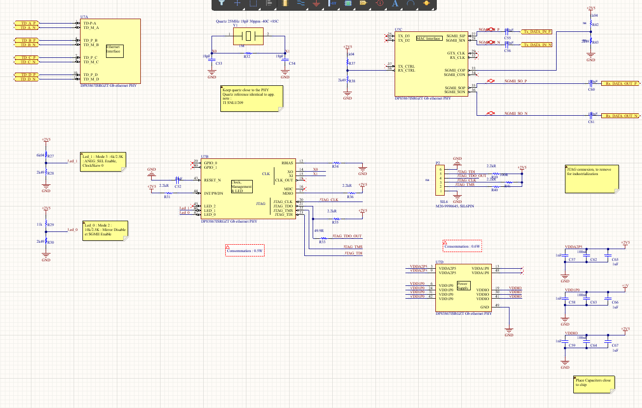
our company uses a design based around DP83867ISRGZT PHY to implement Ethernet contactless 1000BaseT communications. I am currently troubleshooting the design as I noticed cycling power sometimes cause the PHY to hang up randomly. I am aware that a POR is performed at power up and that HW reset can be performed applying a RESET_N low for at least 1uSec. RESET_N in our design is connected to a single 10nF resistor to supply the pulse at powerup. Does RESET_N have an internal pullup or do we need to implement an external one for clean POR operation? schéma PHY.png

Thx & Rgds

  • Hi Serge,

    RESET_N has an internal pullup, so you should see this rise if probing the line. By 'hang up randomly' what issues is the PHY showing? (no register access, no link up,...). What is the rate of failure that you see? (1/10 power cycles hang up,...)

    From the schematic it seems the MDC/MDIO bus is not being used. Can you elaborate on how you're strapping the PHY into the correct mode? I also do not see a value on the RBIAS resistor in this image so double check this is correct.

    Best,

    Shane

  • Hello Shane (long time no hear :)

    I'll show you the "full picture":

    ...

    This is a design I inherited from previous engineers and in production. PHY is configured thru external resistors (we don't have any uC onboard to configure the PHY nor do we use the the JTAG). I have had reports from customers that when Ethernet is desynced or lost, the only way to get it going again (all we do is serialize 100BaseT into  SGMII and back) is to cycle power. which is why I am looking into POR or a way to implement a watchdog. RBIAS is connected to GND thru a 11K resistor.

    Rgds

    Serge

  • Hi Serge,

    By 'When ethernet is desynced or lost' I assume you mean when the link is lost it will not come up again until the PHY is power cycled. Is this correct? The link status will be shown on LED_0 so if this stops asserting after the hang-up condition then something is preventing the PHY from linking up.

    Since a power cycle fixes this, I agree there may be an issue with the power on timings. Clocking and MDI implementation would also be good to double check. We have a DP83867 troubleshooting guide with a list of health checks to perform that I recommend reading through to see if we can narrow down where the issue is happening.

    Without register access the debugging we can do is limited to the hardware implementation of the PHY, so creating a watchdog will be more difficult. I suppose you could base a watchdog on the link going down, however this would activate even if someone were to just unplug the cable. I'm unsure if this is acceptable in your application.

    Looking at the schematic:

    1. The decoupling network on the voltage rails does not meet the recommendations in the datasheet. I recommend adding capacitors so that each pin has a 0.1uF and 1uF to GND for decoupling:

    2. I notice your pullup on LED_0 is 11K rather than the recommended 10K. Double check that this strap is in the correct voltage range on powerup:

    Best,

    Shane

  • Hello Shane,

    You are correct in your assumptions regarding desynching. the problem we have with debugging is that LED_0 is used as a configuration strap for mirror disabled & SGMII Enabled and not as a status indicator (which would be useful). I guess we could use JTAG to read registers status when the IC crashes? I have read the troubleshooting guide and we will have to perform a redesign to ensure we use the IC in accordance with TI specs. I agree ith you the 11K R29 should be 10K.

    Cheers

    Serge

  • Hi Serge,

    LED_0 can simultaneously work as a strap and as a status indicator. The strap resistor is weak enough that the LED can still operate with a strap resistor in parallel:

    Transparently, we do not have equipment for using the JTAG interface on this device in our lab, so JTAG implementation will rely on your knowledge/testing.

    Best,

    Shane

  • Ok, thx Shane.

    Does that literally mean the PHY reads voltage level upon startup on LED_0 & LED_1 pins, then reverts to operation?

    use an LED between Rlo and GND and carefully compute Rlo & Rhi values to have the voltage I desire for mode of opertation?

    Thx

    Serge

  • Hi Serge,

    Does that literally mean the PHY reads voltage level upon startup on LED_0 & LED_1 pins, then reverts to operation?

    Yes that is correct. The PHY will sense the voltage on all strap pins (including LEDs) at startup to determine the set configuration. Once the straps are sampled, strap pins will switch to their normal function.

    use an LED between Rlo and GND and carefully compute Rlo & Rhi values to have the voltage I desire for mode of opertation?

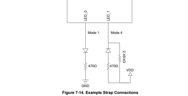
    The voltage divider should be in parallel with the LED used, not in series. For example, the image below shows how Mode 1 and mode 4 can be implemented:

    If you need mode 3 or mode 2, the LED will be active-high, and so the LED should be in parallel with Rlo. This would be a similar approach to the Mode 1 implementation in the above image, but with a parallel strap network on the LED_0 pin.

    Best,

    Shane

  • Hello Shane,

    LED should be in parallel with Rlo

    ok got it. Since a LED usually has a fairly high forward voltage,

    but that mean connecting the LED straight into the PHY without load resistor (we use VDDIO=2.5V). Isn't there a chance of blowing LED_0 output when/if LED_0 goes high to 2.5V?

    Thx

    Serge

  • Hi Serge,

    The LED should have a current limiting resistor in series. In our datasheet example this is 470 ohms.

    The strap resistor will be a much larger value, and would be in parallel with the LED+ current limiting resistor network.

    Best,

    Shane