A related question is a question created from another question. When the related question is created, it will be automatically linked to the original question.
If you have a related question, please click the "Ask a related question" button in the top right corner. The newly created question will be automatically linked to this question.
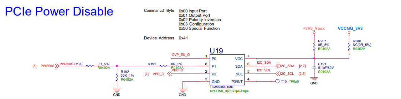
Generally, a 0.1-uF capacitor is placed on VCC, as close to the device as possible
Verify the schematic pinout matches the data sheet pinout
Good
DTM package
Check that the pullup resistors are present on the SDA and SCL net within the schematic.
Check pages 2,7
Unused GPIO pins configured as INPUT’s are biased to either VCC or GND via resistor
Good
Most of TI's IO expander portfolio do not include internal pull-up resistors on the p-port pins; the exceptions are PCF8575, PCF8574, PCF8574A, TCA9555|PCA9555, PCA9554|TCA9554, and TCA9554A|PCA9554A and therefore can be left floating.
An alternative approach is after powering up the device, any unused p-port pins can be set as an output (does not matter if set high or low).
TCAL agile IO expanders also have the ability to enable internal PU or PD resistors.
GPIO pins configured to OUTPUT must be current limited externally
Verify
i.e. the push-pull output sources current from VCC or sinks current to GND. Ensure that the output is never tied directly to VCC, GND, or to another output that could contend with the push/pull output. Otherwise, IOH/IOL may not be limited and could exceed abs. max conditions of the device which could cause permanent damage.
Device address is unique on the bus unless using an I2C switch or I2C MUX to resolve conflicts
Verify
Check the rest of the devices on page 2 and 7 for unique I2C addresses
If the device has a /RESET pin, bias the pin high (preferably with a pull-up resistor) after powering up.
n/a
If the device has a /INT pin and the /INT pin is used, tie this pin to a pull-up resistor.
Good
P3/INT looks to be unused. Can be left floating. If P3 is configured to INPUT, use a pull-up or pull down resistor to keep the pin from floating.