TPS3705: Request for TPS3705-33DR SchematicDear Team, I am facing an issue while designing a circuit using the TPS3705-33DR. The TPS3705-33DR is powered with a 3.3 V s

Part Number: TPS3705
Other Parts Discussed in Thread: TPS35

Dear Team,

I am facing an issue while designing a circuit using the TPS3705-33DR.

The TPS3705-33DR is powered with a 3.3 V supply, and the same 3.3 V supply needs to be monitored. It would be helpful if you could provide a reference schematic for this configuration, including details on the pin connections (which pin should be connected to what).

Please refer to the attached file for the circuit details.

Thank you for your support. I look forward to your response.

Thanks and regards,
Bhakti

Screenshot 2026-08-03 182558.png

  • Hi Bhakti,

    Here is a schematic. With the resistor divider, place the resistors as close to the device as possible to reduce noise coupling. Aswell as placing the 0.1uF decoupling cap as close as possible to the device.

    Do you plan on using the MR and PFO separately?  And are you planning on using the watchdog features?  If not, we can recommend some parts that might fit your use case better.

    Best,
    Miah Miner

  • Hi Miah,

    Thanks for your reply.

    If I am trying to monitor a 3.3 V signal, is a voltage divider required, or will the internal threshold of TPS3705-33DR

    be sufficient?

    If the internal threshold voltage is sufficient, should I connect the 3.3 V signal directly to the PFI pin?

    Also, can I make the following connections?

    • Connect directly PFO* to MR*
    • Connect RESET* to the NRST pin of the MCU
    • Connect WDI to a GPIO pin of the MCU
    • Connect WDO* to a GPIO pin of the MCU

    Please let me know if these connections are correct.

    Thanks & Regards,

    Bhakti

  • HI Bhakti,

    You will need a resistor divider for the input of the PFI pin. The PFI input voltage needs to be 1.25V.

    Yes, all of the connections you listed will work! 

    Best,
    Miah

  • Hi Miah,

    Thank you for the clarification.

    • Could you please suggest the values for R284 and R285 based on the image below, assuming a 3.3 V input is applied?
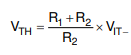
    • Can we use 1.25 V = VIT− in place of the equation shown below to calculate VTH for different input voltages, such as 3.3 V, 5 V, 12 V, and so on?

    Thank you in advance for your support.

    Thanks and regards,

    Bhakti


  • Hi Bhakti,

    What is the threshold voltage you wish to use?  Once you have as chosen threshold voltage, that will be the VTH value. 1.25 is the VIT- value.  Then pick a value for R2 and solve for R1.

    I would suggest using TPS35D (TPS35DA40GCJDDFR)  instead of TPS3705 for your use case.  VDD is monitored for this device as well, so PFI doesn’t seem like a need for this layout. And since the PFO and MR are tied, they aren’t in use.

    TPS35 offers the same watchdog function as TPS3705, but without the PFI/O use. TPS35 also has set thresholds, so an external resistor divider won’t be necessary.

    Best,
    Miah Miner