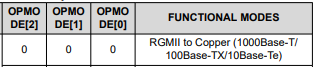
Part Number: DP83869EVM
Other Parts Discussed in Thread: DP83869
Wiring connection Explanation:
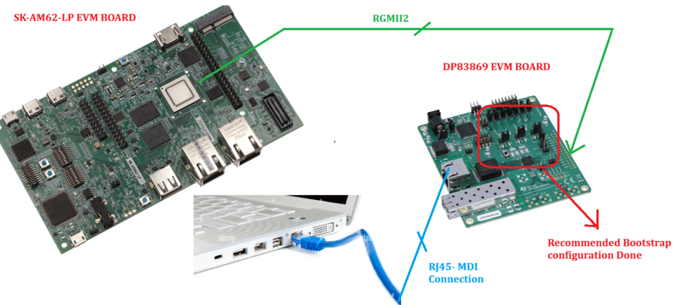
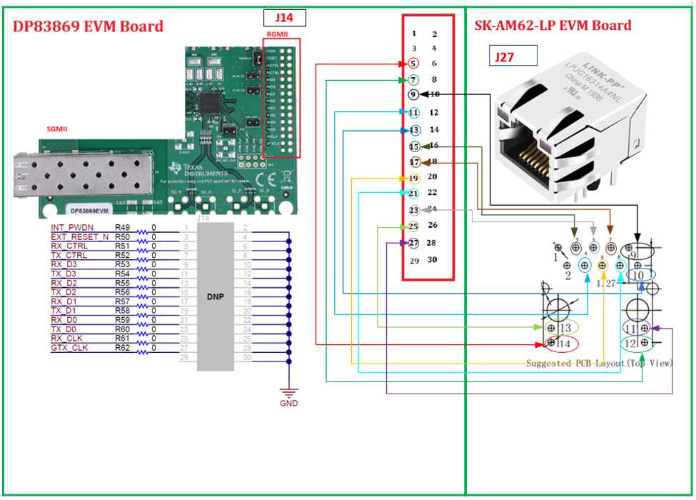
Objective: RGMII interface to MDI interface conversion
We are trying to validate the RGMII interface to MDI interface (RJ45 Connection) at 1Gbps bandwidth.
What Worked (10 Mbps)
Bidirectional ping confirmed at 10 Mbps (forced via ethtool -s eif1 speed 10 duplex half autoneg off)
iperf throughput validated at 10 Mbps
Both TX and RX frames are incremented (tx_good_frames and rx_good_frames both non-zero)
PHY correctly detected at MDIO address 3 (phy_id = 0x2000c3d8)
Link comes up (with flapping) confirms wiring direction is correct
What Did NOT Work (100 Mbps / 1000 Mbps)
At 100M: Link comes up but RX is completely dead — tx_good_frames increments, rx_good_frames = 0
At 100M: Link flaps continuously (Up/Down every ~1 second)
Questions:
- Do we need to install DP83869 driver separately...? or its part of uboot kernal driver...?
- What is maximum allowable trace length for the RGMII interface, is this connection length valid...?
- Able to see link active state for 10/100/1000Mbps, But it is working ping command only for 10Mbps, verified iperf3 throughput for the same. What is the issue..?
- Have Probed both RX & TX clock able to see 125Mhz frequencies.
- RGMII interface interrupt pin (INT_PWDN) from DP83869 EVM to processor required to connect to processor...?
- MDC & MDIO interface works properly and able to configure Read the PHY address.
- What is the auto negotiation boot strap followed for 1Gbps bandwidth.
- Is there application notes or forums to resolve this issue.?