TCAN4550: TCAN4550 schematic review

Part Number: TCAN4550

Hi TI,

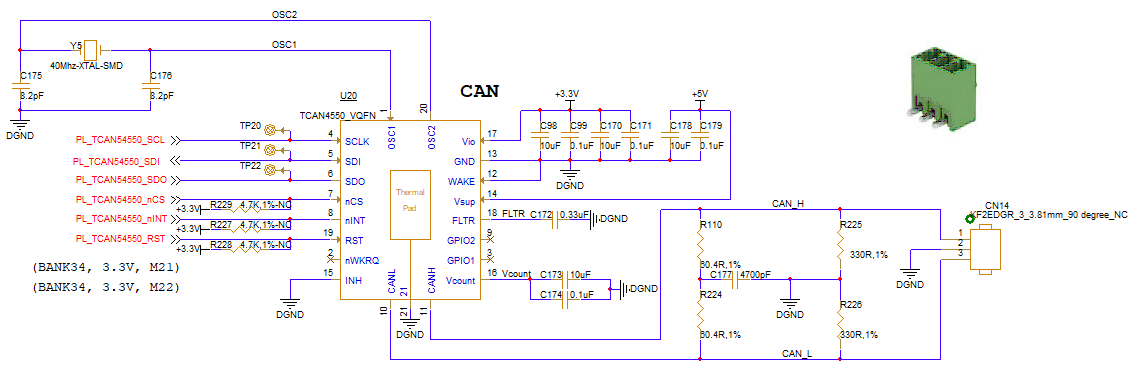
I am trying adopt TCAN4550 in my FPGA board, the below is my TCAN4550 schematic, would you please help to review wether it is OK?, expecially pin INH , nWKRQ and WAKE are OK?, I would like to disable wakeup function for this chip.

Wether do PL_TCAN54550_nCS, PL_TCAN54550_nINT, PL_TCAN54550_RST need pull up through resistor?


Jerry Wu
 

TCAN4550.bmp

  • Hello Jerry,

    I have reviewed the schematic and I have the following comments:

    - The minimum VSUP supply voltage is 6V, the device cannot be used with a 5V supply.  Tis is because there is an internal 5V LDO that supplies the CAN transceiver and it requires some overhead voltage in order to create a regulated 5V.  The device will enter an undervoltage lockout protected state when VSUP = 5V.

    - The VIO does not draw a lot of current and does not need this amount of capacitance.  The majority of the device is supplied from the VSUP pin.  The VIO supply is used as the voltage reference for the digital IO level shifter circuits and to supply the crystal/clock circuit connected to the OSC1 and OSC2 pins.

    - The RST pin is active High, meaning it needs to be held Low during normal operation.  A pull-up resistor is not common and would require the PL_TCAN4550_RST signal to continuously pull the RST pin Low during operation to prevent a device reset.  A pull-down resistor is more common and a short pulse high on the PL_TCAN4550_RST signal would only be required to create a reset event.

    - I don't know the purpose of the 330R resistors R225 and R226.  These are not common.

    - The INH pin should NOT be connected to GND.  This pin is driven to the VSUP voltage when the device is in Standby and Normal modes and connecting it to GND would create a large current flow between VSUP and GND.  If the INH pin is not needed, is should be left floating as a no connect.

    - A series resistor should be placed between the OSC1 pin and the crystal to help optimize the clock circuit for stable operation.  A 0-ohm resistor can be used as a placeholder and replaced with a larger value if necessary.  Usually a value less than 100 ohms is sufficient when a series resistance is needed.  Please review the following documents for more information.

    TCAN455x Clock Optimization and Design Guidelines Application Report (Link)

    TCAN455x-Q1 Peripheral Circuit and Clock Design Application Note (LInk)

    Regards,

    Jonathan

  • Hi Jonathan,

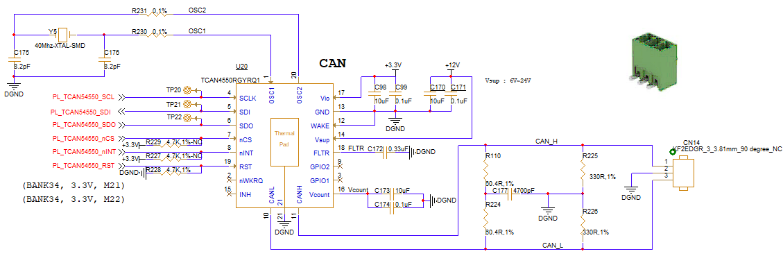
    Thanks for your reply, I had made some changes on TCAN4550 schematic according to your comments,  the new TCAN4550 schematics is as below

    major changes :

    1. change +5V to +12V for Vsup

    2. pull low regisistor (4.7K) for TCAN4550_RST

    3. remove 10uF and 0.1uF from Vio path

    4. keep INH as no connected

    5. add R230 (0R,1%) , R231 (0R,1%) for OSC1 ,OSC2

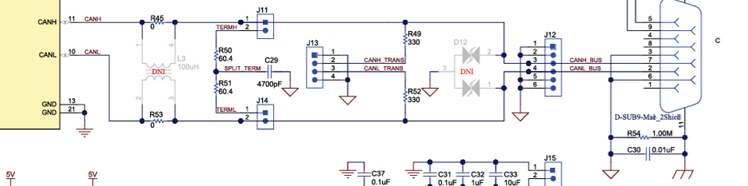
    About R225 and R226 which are refer to TCAN4550 EVM (photo 2 : R49, R52) schematic as below, should I keep these two regisistors out ?

    Jerry Wu


      photo 1

     photo 2

  • Hi Jerry,

    The changes look good.  I would recommend removing the 330 ohm resistors if you don't have a need to include them.  If you will notice on the EVM, these 330 ohm resistors are in series with a header and are not connected directly to GND.  The purpose of this header on the EVM is to provide an injection point for transient signals, or for a common mode bias, etc.

    In your schematic these resistors are directly connected to GND which will act as a very strong pull-down resistance on the CANH and CANL bus and will distort the signals.

    If you want to have an additional test point header on your CAN bus similar to the EVM, then you should connect the 330 ohm resistors to a test point and not to GND. But these resistors are not needed in an actual application and are only provided on the EVM to help with lab related tests.  Therefore you can safely remove them from your schematic, or make them uninstalled.

    One additional option would be to replace them with some small filter caps such as 20pF that can help filter noise from the CAN signals.

    Regards,

    Jonathan

  • Hi Jonathan,

    Your reply had resolved my questions , thanks very much for your help to review my TCAN4550 schematic

    Jerry