This thread has been locked.

If you have a related question, please click the "Ask a related question" button in the top right corner. The newly created question will be automatically linked to this question.

TLIN1021A-Q1: Duty cycle patterns and related timing parameters

Part Number: TLIN1021A-Q1

Hello, Team,

We would like to understand the timing parameters given in the datasheet, especially ones related to duty cycle D1 ~ D4. We are a bit confused with what are the relationship between these parameters and how we should use them when designing a system.

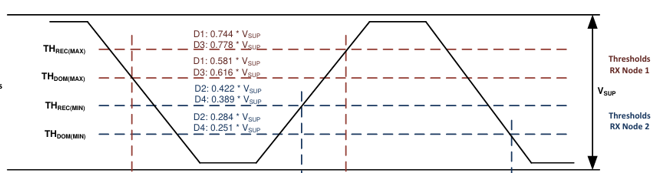
Below is the combined image of Figure 8-9 and 8-11.
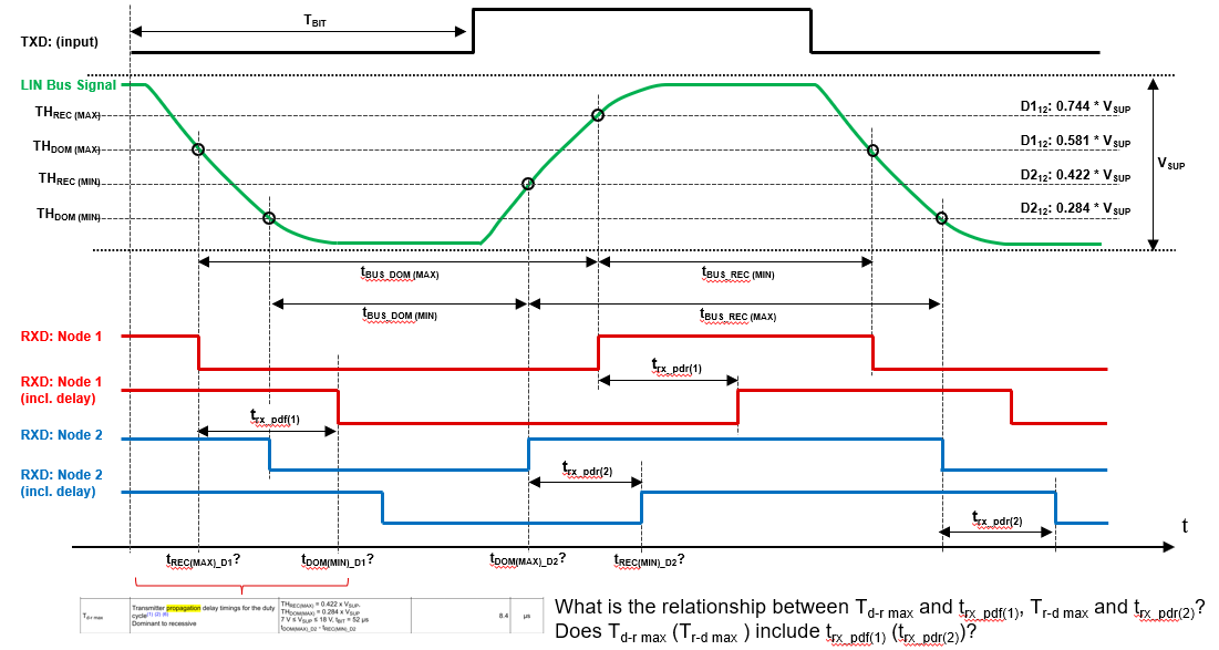
image.png

Main questions are:

  • What is the relationship between Td-r max and trx_pdf(1), Tr-d max and trx_pdr(2)?
    • Does Td-r max (Tr-d max ) include trx_pdf(1) (trx_pdr(2))?
  • Based on Figure 8-11 and Td-r max spec in the Electrical Characteristics, it appears there is a discrepancy in the definitions: THREC(MIN), rather than THREC(MAX), is equal to 0.422 x VSUP, and THDOM(MIN), rather than THDOM(MAX), is equal to 0.284 x VSUP. Could you please clarify if this is an error in the text? 

    image.png
    image.png

Best,
Masaru

  • Hi Masaru,

    1. These are two different segments of the total TXD to RXD signal path, not the same measurement. Td‑r max / Tr‑d max ("Transmitter propagation delay timings for the duty cycle") are purely transmitter‑side (TXD → LIN) delays. They are defined per the ISO 17987 duty cycle specification (Figure 8‑8/8‑9), and are computed from bus threshold crossing times. trx_pdf / trx_pdr are receiver‑side (LIN  → RXD) propagation delays, defined via Figure 8‑10 (test circuit) and Figure 8‑11 (propagation delay waveform), measured with a fixed RRXD/CRXD load. So, they don't include each other.

    2. You are correct, this does appear to be typo in Td-r max spec in the Electrical Characteristics. THREC(MIN) = 0.422 × VSUP, THDOM(MIN) = 0.284 × VSUP.

    Regards,

    Sean