This thread has been locked.

If you have a related question, please click the "Ask a related question" button in the top right corner. The newly created question will be automatically linked to this question.

SN65HVD3082E: Ti RS485 communication AC termination parametter

Part Number: SN65HVD3082E


1.we want to using AC Termination but we don't known how to seting those paratema ,Cterm, R_Pull up,R_Pull down ,does have any caculation doc or white paper can  support this? 

2.Data Rate Medium what is mean for ?AC Termination  it suitable for our project Baud rate: 9600 bit? 

3.Can you share the acturely application circuit ?
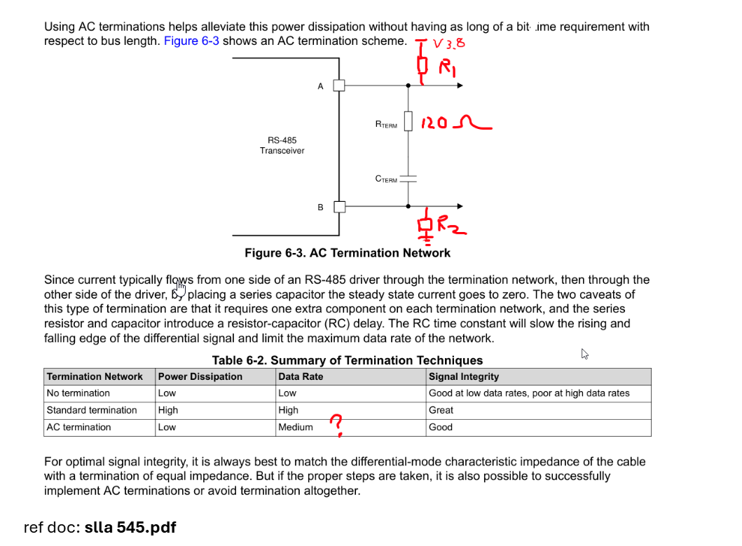
 image.png

source : no iso, power supply 3.8V, 1 master ,20 slave device,eatch slave connect one 120 terminal resistance ,low power sonsumption, Baud rate: 9600 bit, Break application

2026-09-03_11-38-47.png

others question :  we have a customer using those way connect ,what is the function of this diode ?
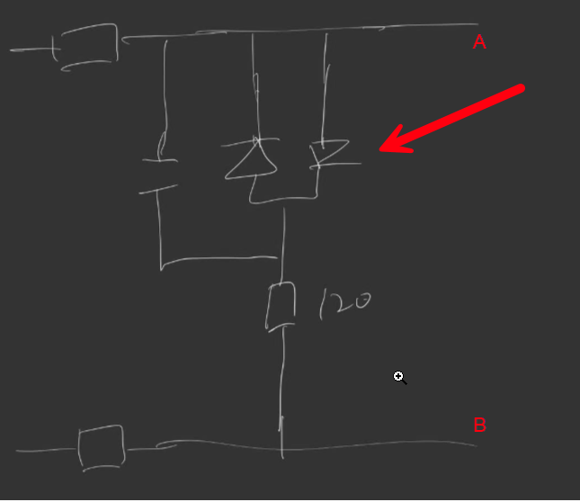
image.png

refer doc

www.ti.com/.../slla545.pdf

  • Hi Yandong,

    1.we want to using AC Termination but we don't known how to seting those paratema ,Cterm, R_Pull up,R_Pull down ,does have any caculation doc or white paper can  support this? 

    You can refer to this doc for AC termination sizing help. This device has internal failsafe biasing so you don't need external failsafe biasing as long as every other node in your system has it. If you do need external failsafe biasing, you can you this note has a guide.

    2.Data Rate Medium what is mean for ?AC Termination  it suitable for our project Baud rate: 9600 bit? 

    "Medium" refers to the relative speed compared to unterminated and standard termination. Standard has the highest possible data rate, unterminated the slowest, and ac terminated is somewhere in between. Your speed requirements should be fine, just note the line in the first app note I linked: "the resulting RC time constant should be less than or equal to 10% of the unit interval (bit width)".

    3.Can you share the acturely application circuit ?

    The first app note I linked above has some waveforms from an ac terminated system (Figure 8). You should also note that you should not terminate every node of the system. Just the nodes at the two ends of the cable for this half-duplex setup.

      we have a customer using those way connect ,what is the function of this diode ?

    I'm not entirely sure what those diodes are for. I couldn't find an example of similar circuitry in the reference doc you linked at the bottom. If I missed it feel free to let me know.

    -Ethan White