TIOS102: The lackage current measuring method for TIOS102

Part Number: TIOS102

Hi,

We want to measure the lackage current for the output sinking current(low-side dirver) in PNP mode, and now, the current is about 10mA-40mA when there are no load, but it is 10uA in the datasheet.

We consider it is the error for the measuring method and we need to know how to meausre the lack current, and the below is the option for this method:

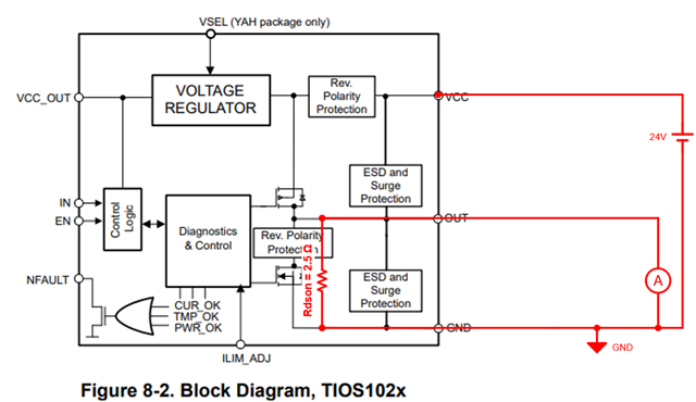
  1. Connect the OUT pin in series with the ammeter and directly to GND;
  2. Connect the ammeter in series with the OUT pin and connect 120R in series to GND;
  3. Other measuring method?

The below is the screenshot from the datasheet and we need the lackage current is less than 1mA;
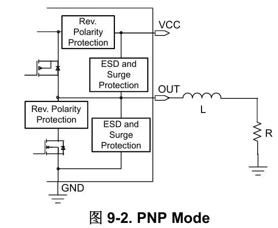
image.png

image.png

  • Hello Zhang,

    I assume you are referring to this 10uA specification for the leakage current during a reverse polarity event.  Please note that this is when the device has disabled the low-side driver because it has detected the OUT pin voltage has been pulled below GND by 3V.  Please note the V(OUT to GND) = -3V condition.

    Please refer to my response to your previous thread on the TIOS102: The leakage current in reverse polarity is high (Link).

    An ammeter without a series resistance would be the preferred test method.

    A 120 ohm resistor located in series between the OUT pin and GND will cause current to flow because the OUT pin is connected to GND through the driver transistors that have an Rdson of approximately 2.5 ohms.  But the OUT pin and GND pin are also connected together through an external 120 ohm resistor.  This creates a closed circuit where the external load and the internal Rdson are in parallel and causes a current to flow.

    Note that using an external load between OUT and GND is a valid configuration for PNP mode, but not NPN mode which is being used in your test by setting the EN and IN pins High.

    Regards,

    Jonathan