AM62A7-Q1: Am62a7 SDIO phase adjustment issue

Part Number: AM62A7-Q1
Other Parts Discussed in Thread: AM62A7, AM62D-Q1, AM62A3, AM62A1-Q1,

Hi, team

We use the MMC1 interface of am62a7 to conduct SDIO communication with the Wi-Fi module. Due to the need for sufficient setup and hold time, we adjust the phase of the clock through devmem 0xfa0810c. During the testing, we found that:
1. When the SDR104 mode was configured with CLK = 100M and devmem was used to adjust the phase, the establishment and hold times sent by the SOC, as well as the tODLY and tOH received by the SOC, could all be phase-adjusted.
2. When the SDR25 mode was configured with CLK = 50M and devmem was used to adjust the phase, the establishment and hold times sent by the SOC could be changed, but the tODLY and tOH received by the SOC could not be changed.
3. When the High-speed mode was configured with CLK = 50M and devmem was used to adjust the phase, the times sent by the SOC could not be changed.
In modes 2 and 3, we also tried to adjust the phase by regulating the itap write register, but the result was still unadjustable.

Under the above circumstances,
Since the measured tODLY and tOH values for the 50M mode do not meet the requirements, we plan to adjust the SDIO to 50M and adjust the phase to ensure that each time is in line with the standards of SDIO 3.0. However, neither the 2 or 3 mode currently configured is working. Could you please help us find out if there are any other solutions?
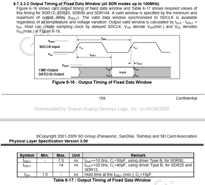
image.png

Thanks,

Xiwen

  • Hi Xiwen,

    Thank you for your query !

    Please allow me some time to analyze your inputs. I also may need to internally discuss on a possible solutions.

    I hope I can follow-up in a day or two.

    Your patience is appreciated !

    Best Regards,

    Anastas Yordanov

  • Hi Xiwen,

    I would like to apologize to you for my late reply !

    As per my discussion with our AM62Ax MMC/SD/SDIO hardware interface expert:

    "We only support the PHY delay values defined in the “MMC1/MMC2 DLL Delay Mapping for all Timing Modes” table found in the AM62Ax Datasheet. You should not be changing the values.

    The configurations defined in the table should produce an output that is compliant to the SD Card standard, assuming you design a PCB that is compliant to the PCB Connectivity Requirements defined in the “MMC1/MMC2 Timing Conditions” table.

    Thank you

    Best Regards,

    Anastas Yordanov

  • Hi,Anastas

    Thank you for your response.
    Our actual application is that the other end of MMC1 is connected to the WIFI module. The CLK phase value is adjusted based on the establishment and maintenance time of the measured waveform. If we do not make the adjustment, the time margins of tsetup, thold, tODLY, and tOH will be too short, which may cause intermittent connection failures of WIFI.
    Therefore, we would like to know how to adjust the phase time under the 50M mode condition.

    Thanks,

    Xiwen

  • Hello Liu Xiwen,

    The key reason for the different behavior you observed across the three modes lies in how the AM62A7 PHY DLL (OTAP/ITAP delay lines) is engaged depending on the configured speed mode. Please refer to the PHY_CTRL register (0xfa0810c) DLL mapping table below:

    Mode

    OTAPDLYENA [20]

    OTAPDLYSEL [15:12]

    ITAPDLYENA [8]

    ITAPDLYSEL [4:0]

    High Speed (3.3V, 50MHz)

    NA

    NA

    0x1

    0x0

    UHS-I SDR25 (1.8V, 50MHz)

    0x1

    0xF

    0x1

    0x0 (Fixed)

    UHS-I SDR104 (1.8V, 100MHz)

    0x1

    0x6

    0x1

    Tuning

    This explains your three observations as follows:

    • SDR104 @ CLK = 100MHz- Phase adjustment works (TX and RX): SDR104 has the DLL fully active on both the output (OTAP) and input (ITAP via tuning) paths. Therefore, adjusting the phase register via devmem correctly shifts both the TX output timing (tsetup, thold) and the RX input sampling point (tODLY, tOH). This is the expected and fully supported behavior.
    • SDR25 @ CLK = 50MHz- TX adjustable, but RX (tODLY/tOH) NOT adjustable: In SDR25, the output delay (OTAP) is active with OTAPDLYSEL = 0xF, which is why the TX output timing responds to phase adjustments. However, ITAPDLYSEL is fixed at 0x0 in this mode, there is no input DLL tap delay applied. Writing ITAP values via devmem or the itap register has no effect because the PHY uses a fixed half-cycle capture mechanism for the RX path at 50MHz. This is why tODLY and tOH cannot be shifted.
    • High Speed @ CLK = 50MHz- Neither TX nor RX adjustable: In High Speed mode (3.3V), both OTAPDLYENA and OTAPDLYSEL are marked NA, meaning these register fields have no functional effect in this mode. The PHY does not route the data path through the DLL delay chain at all. Therefore, neither devmem writes to OTAP nor ITAP registers produce any measurable change on the waveform. This behavior is by design and is documented in the AM62A7 datasheet.

    Since ITAP adjustment is not available in SDR25 or High Speed 50MHz modes, we recommend the following alternatives to achieve sufficient tODLY and tOH margins at 50MHz:

    • Option 1 – Switch to DDR50 Mode UHS-I DDR50 operates at 50MHz with 1.8V signaling, providing the same clock frequency while enabling full DLL control on both TX and RX paths:
      • OTAPDLYENA = 0x1, OTAPDLYSEL = 0x9
      • ITAPDLYENA = 0x1, ITAPDLYSEL = Tuning

    With DDR50, both OTAP and ITAP are fully active and adjustable, giving you complete control over tsetup, thold, tODLY, and tOH — exactly as you observed in SDR104. Please confirm that your Wi-Fi module supports DDR50, and update the device tree accordingly:

    ti,otap-del-sel-ddr50 = <0x9>;

    And configure ITAP via the tuning process for itap-del-sel-ddr50.

    • Option 2 – Reduce Clock to 25MHz (SDR12) SDR12 at 1.8V, 25MHz has OTAPDLYENA = 0x1, OTAPDLYSEL = 0xF. At half the clock frequency, the timing margins for tODLY and tOH are naturally doubled, which may resolve the marginal timing without requiring any tap adjustment. This is a lower-risk option if throughput requirements allow.
    • Option 3 – Improve PCB Signal Integrity Since the ITAP path cannot compensate for board-level delay mismatch in SDR25/High Speed modes, we recommend reviewing the PCB trace routing between the AM62A7 MMC1 interface and your Wi-Fi module:
      • Trace delay mismatch between CLK and DAT lines should be kept within 100ps (as specified in the AM62A7 datasheet Table 6-103 for SDR25 and below)
      • Reducing asymmetry between CLK and DAT signal paths can shift the effective tODLY and tOH at the SoC input into a compliant range without requiring register-level adjustment

    Additionally, please confirm that VDDSHV5 (the supply for MMC1) is correctly configured at 1.8V when operating in SDR25 mode. High Speed mode requires 3.3V and, as shown above, has no DLL support, which makes it unsuitable for applications with marginal timing.

    "MMC2 is recommended for implementing the embedded SDIO interface. MMC2 CLK, CMD, and DAT[3:0] signal functions have been implemented with SDIO buffers and are powered by VDDSHV6, which can be operated at 1.8V or 3.3V."

    The PHY DLL configuration and timing behavior for MMC2 are identical to MMC1, so all of the above applies equally. However, MMC2 has been explicitly validated on the AM62A7 SK for SDIO use cases, which may help simplify your bring-up.

    Mode

    OTAP Active?

    ITAP Active?

    tODLY/tOH Adjustable?

    Recommendation

    SDR104 @ 100MHz

    Yes

    Tuning

    Yes

    Working — use as reference

    SDR25 @ 50MHz, 1.8V

    Yes

    Fixed

    No

    Switch to DDR50 @ 50MHz

    High Speed @ 50MHz, 3.3V

    NA

    NA

    No

    Not viable for marginal timing

    Our primary recommendation is to switch to DDR50 mode, which maintains your 50MHz clock frequency while enabling full DLL control for both TX and RX timing adjustment.

    Best Regards,

    Borislav Lazarkov

  • Hi Xiwen,

    I am just checking, if you had the chance to test option 1 ?

    Let us know.

    Thank you !

    Best Regards,

    Anastas Yordanov