DS90UB927Q-Q1: DS90UB927Q Test Pattern Generation Reference for 1920×384 @ 60Hz Display

Part Number: DS90UB927Q-Q1
Other Parts Discussed in Thread: DS90UB928Q, ALP

Hello Team,

We have the following setup:

  • Serializer: DS90UB927Q
  • Display Resolution: 1920 × 384 @ 60 Hz
  • Serializer-Deserializer link is established and we would like to use the internal test pattern generator to validate the FPD-Link connection independently of the video source.
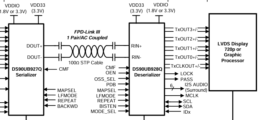
image.png

Could you please share any application note, reference guide, EVM example, or register configuration for enabling the test pattern generation on the DS90UB927Q/DS90UB928Q pair, particularly for a custom resolution of 1920 × 384 @ 60 Hz?

Any example configuration or timing-register settings would be highly appreciated.

Thank you for your support.

Best Regards,
Shammi 

  • Hi Shammi,

    Could you please share the display timings for the 1920 x 384 @ 60 Hz, including the horizontal and vertical active, total, front porch, sync width, and back porch. Then I can share a script for internal test pattern generation. The display panel's datasheet should have this information.

    Best regards,
    Ikram

  • Clock: 49.95 MHZ

    H Active: 1920 

    V Active : 384

    H Sync : 10

    Vsync : 3

    H Back Porch : 32

    H total: 1962

    V Back Porch: 24

    V Total: 424

    Best Regards,

    SHAMMI

  • Hi Shammi,

    Display Timings:

    ## Total Horizontal Pixels = 1962
    ## Total Vertical Lines = 424
    ## Active Horizontal Pixels = 1920
    ## Active Vertical Lines = 384
    ## Horizontal Back Porch = 32
    ## Vertical Back Porch = 24
    ## Horizontal Sync = 10
    ## Vertical Sync = 3
    ## Horizontal Front Porch = 0
    ## Vertical Front Porch = 13
    ## Horizontal Sync Polarity = Positive
    ## Vertical Sync Polarity = Positive
    ## Bits per pixel = 24 = 0x18
    ## Pixel Clock = ~49.95 MHz

    In your timings, what is the horizontal front porch? It seems unusual for HFP to be 0.

    According to the timings shared, I found V front porch = 13, but HFP = 0. Please check the datasheet for the actual HFP values and replace the HFP and HTotal in the script

    Also, I assumed the Hsync, Vsync, polarity to be positive. If that is not the case, it should be updated in the script.


    Script for Test Pattern with 927:

    This script if for 927 internal PatGen. The configuration details are also shared in this app note: https://www.ti.com/lit/an/snla132g/snla132g.pdf

    ## Total Horizontal Pixels = 1962 = 0x7AA
    ## Total Vertical Lines = 424 = 0x1A8
    ## Active Horizontal Pixels = 1920 = 0x780
    ## Active Vertical Lines = 384 = 0x180
    ## Horizontal Back Porch = 32 = 0x20
    ## Vertical Back Porch = 24 = 0x18
    ## Horizontal Sync = 10 = 0xA
    ## Vertical Sync = 3 = 0x3
    ## Horizontal Front Porch = 0 = 0x0
    ## Vertical Front Porch = 13 = 0xD
    ## Horizontal Sync Polarity = Positive
    ## Vertical Sync Polarity = Positive
    ## Bits per pixel = 24 = 0x18
    ## Pixel Clock = ~49.95 MHz = 50 MHz (= 200 MHz * M/N, where M = 1, and N = 4)


    serAddr = 0x18
    
    
    board.WriteI2C(serAddr,0x66,0x03) # N = 4 = 0x4
    board.WriteI2C(serAddr,0x67,0x03)
    
    
    board.WriteI2C(serAddr,0x66,0x07) # 8 LSB active horizontal
    board.WriteI2C(serAddr,0x67,0x80)
    
    board.WriteI2C(serAddr,0x66,0x08) # 4 LSB active vertical and 4 MSB active horizontal
    board.WriteI2C(serAddr,0x67,0x07)
    
    board.WriteI2C(serAddr,0x66,0x09) # 8 MSB active vertical
    board.WriteI2C(serAddr,0x67,0x18)
    
    board.WriteI2C(serAddr,0x66,0x04) # 8 LSB total horizontal
    board.WriteI2C(serAddr,0x67,0xAA)
    
    board.WriteI2C(serAddr,0x66,0x05) # 4 LSB total vertical and 4 MSB total horizontal
    board.WriteI2C(serAddr,0x67,0x87)
    
    board.WriteI2C(serAddr,0x66,0x06) # 8 MSB total vertical
    board.WriteI2C(serAddr,0x67,0x1A)
    
    board.WriteI2C(serAddr,0x66,0x0C) # horizontal back porch
    board.WriteI2C(serAddr,0x67,0x20)
    
    board.WriteI2C(serAddr,0x66,0x0D) # vertical back porch
    board.WriteI2C(serAddr,0x67,0x18)
    
    
    board.WriteI2C(serAddr,0x66,0x0A) # horizontal sync width
    board.WriteI2C(serAddr,0x67,0x0A)
    
    board.WriteI2C(serAddr,0x66,0x0B) # vertical sync width
    board.WriteI2C(serAddr,0x67,0x03)
    
    
    board.WriteI2C(serAddr,0x66,0x0E) # horizontal and vertical sync polarity
    board.WriteI2C(serAddr,0x67,0x00)
    
    
    board.WriteI2C(serAddr,0x65,0x04) # internal timing, internal clock
    board.WriteI2C(serAddr,0x64,0x05) # enable patgen


    Test Pattern with ALP GUI:

    An easier way to generate the test pattern on your setup will be by using the ALP GUI. The EVM user guides have notes on how to set up the EVMs with ALP GUI.

    On ALP, go to the 927 profile, then:

    • Go to the pattern generator tab
    • Set "Spec" to customized
    • Enter custom display timings for your display for each timing parameter
    • Set "Timing source" to be Internal
    • Hit apply
    • Then check "Color Bars"
    • Check "Enable Generator"

    This should output test pattern from the 927 serializer to 928 DES. The GUI writes the same registers as the script above.

    Note that the 927 and 928 should be connected and the mode strap (set with EVM hardware switches) should be set to the correct modes which work with the display.


    Next steps:

    • Check HS/VS polarity and HFP and Htotal from panel datasheet. 
      • It is unusual for HFP to be 0. Please check the datasheet and use a higher value within the tolerance limits
    • Set up EVMs with power, display connected, and correct mode selections
    • Test with script shared (with HFP updated as needed)
    • Or, test with ALP Pattern Generator tab. 

    Best regards,
    Ikram