DS40MB200: Output enables on the DS40MB200

Part Number: DS40MB200

We use DS40MB200 Port 1 for primary/redundant CML paths.
Please confirm the complete behavior when LB1A = LOW and LB1B = HIGH, with LI_1 and SIA_1 carrying valid AC-coupled CML data:
1. Is SOA_1 actively driven from SIA_1?

2. Is SOB_1 actively driven from LI_1, or is it muted, disabled, high impedance, or static in this state?

3. Is there any supported control state that makes only SOA_1 or SOB_1 electrically idle, high impedance, or near 0 V while the other output remains active?

4. For any disabled or non-driven state, please specify output DC common-mode voltage and impedance, including whether the internal nominal 50 ohm pullups to VCC remain present.
Our requirement is to prevent voltage/back-power on an inactive external redundant cable while the other Port 1 output operates at 2.5 Gb/s. “No valid data” alone is insufficient; we need a documented inactive or isolated output condition.
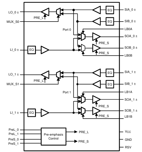
image.png

  • Hi Gage,

    Welcome to the e2e forums.

    Please confirm the complete behavior when LB1A = LOW and LB1B = HIGH, with LI_1 and SIA_1 carrying valid AC-coupled CML data:
    1. Is SOA_1 actively driven from SIA_1?

    Yes, see table 7-2 in the datasheet. 

    2. Is SOB_1 actively driven from LI_1, or is it muted, disabled, high impedance, or static in this state?

    It is actively driven from L1_1, the block diagram in section 7.2 shows this. The mux selection for this output routes from L1_1 to SOB_1 even if the L1A is set low, these are independently routed. 

    3. Is there any supported control state that makes only SOA_1 or SOB_1 electrically idle, high impedance, or near 0 V while the other output remains active?

    No, the SOA_1 and SOB_1 don't have an explicit shutdown in this device. Its possible to route their sources as either loopback, or the input, but they are still CML Drivers.

    4. For any disabled or non-driven state, please specify output DC common-mode voltage and impedance, including whether the internal nominal 50 ohm pullups to VCC remain present.
    Our requirement is to prevent voltage/back-power on an inactive external redundant cable while the other Port 1 output operates at 2.5 Gb/s. “No valid data” alone is insufficient; we need a documented inactive or isolated output condition.

    Because there is no undriven state, they would always present the 50Ohm pullup to VCC. At the outputs the common mode voltage is 2.7V. 

    Best Regards,
    Brandon Fisher