THVD1420: RS485 Circuit Validation

Part Number: THVD1420

Dear Team,

Greetings.

I am designing an RS-485 communication circuit for communication between the indoor and outdoor units of an air-conditioning system. Since the RS-485 A and B signal lines may run close to power lines, there is a risk of induced voltage, electrical noise, and transient surges affecting the communication interface.

I have designed the protection circuit and would appreciate your technical review to confirm whether the proposed design is suitable for this application and provides adequate protection against induced voltages and electrical transients.

In particular, I would appreciate your recommendations regarding the following points:

  1. GDT and TVS protection: I am using a Gas Discharge Tube (GDT) and TVS diodes for surge protection, with their protection paths connected to Protective Earth (PE) rather than directly to the RS-485 circuit ground. Is this a suitable approach for diverting surge currents, or should the protection devices be referenced to the RS-485 IC ground?

  2. Grounding and reference strategy: What is the recommended approach for providing a reference between the indoor and outdoor RS-485 interfaces? Should the communication interface use a dedicated signal reference (GND), a PE connection, or galvanic isolation with a separate reference?

  3. Protection against induced voltage and noise: What additional protection measures would you recommend for the A/B lines, considering their proximity to mains power wiring? Please advise on the suitability of common-mode chokes, TVS diode selection, termination, and cable shielding.

  4. PCB layout and grounding: Please recommend the appropriate grounding and PCB layout practices to ensure effective surge-current diversion without allowing transient currents to interfere with the RS-485 transceiver or other low-voltage circuits.

Kindly review the attached schematic and provide your feedback, including any recommended circuit modifications or additional components required to improve the robustness and reliability of the communication interface.

Thank you for your support.
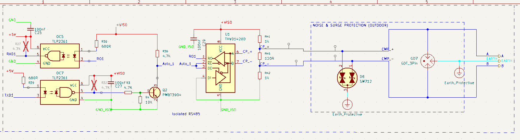
RS485.png

  • Hi Vignesh,

    You can visit our FAQ page which has information on designing RS-485 circuits around surge and other transients, like this page here. 

    Depending on your use case I would also recommend taking a look at our THVD8000 device. This integrates the power and data over the same two cables, which could help reduce cost and complexity for you.

    -Ethan White

  • Thank you for your comments.

    I would appreciate your clarification on one remaining question: should the common connection of the GDT and TVS be connected to DC ground or Protective Earth (PE)?

    I have been unable to find a clear reference or design guideline addressing this specific point.

    Thank you for your support.

  • Hi Vignesh,

    That depends on your system. In your case I think connecting to PE is fine. Connecting to signal (or GND_ISO) ground is also ok, but you have to consider that a large surge could cause a lot of current to rush to signal ground which could shift the common mode voltage of parts connected to it and possibly damage them. I'd be less concerned with the THVD1420 and opto couplers, but I'm not sure if anything else is on that ground node. 

    A few notes about your schematic:

    1. I'd add 10 ohm pulse proof resistors between the TVS diodes and termination resistors on the bus lines. Currently there is nothing protecting the transceiver should the diodes start conducting large amounts of current.

    2. Due to integrated failsafe biasing the two 1k resistors on the bus lines are not required. If you want them to help with noise immunity that is certainly valid. I would just be concerned about how the PE and ISO_GND are coupled (if they are at all, it's not shown in the schematic). Any large shift between the ISO_GND and PE could cause some weird biasing on the B line (between the failsafe resistor and TVS diode) which could cause communication issues. This may or may not be a concern for your system depending on your use case, just wanted to bring it up.

    -Ethan White 

  • Dear Ethan,

    Thank you for your valuable comments.

    Currently, ISO_GND and EARTH are not connected in my design. Could you please clarify whether this arrangement could cause any issues with the RS-485 protection circuit or its surge protection performance?

    If a connection between ISO_GND and EARTH is recommended, I would appreciate it if you could share a reference design or provide guidance on how to implement it correctly. I have not previously worked with this type of ground coupling, so your recommendations would be very helpful.

    Additionally, I will use the 10 Ω pulse-proof resistor as you suggested.

    Thank you for your support and guidance.

    Vignesh

  • Hi Vignesh,

    This is starting to fall out of my area of expertise. I'm going to transfer this thread to our dedicated ISO team.

  • Vignesh,

    I'll look into this thread and get back to you by end of business 10/22/2026.

    Regards,

    Eric Hackett 

  • Vignesh,

    You should leave them disconnected, how they are now is correct. Connecting them would undermine the established isolation barrier and expose the transceiver to ground potential differences of the indoor and outdoor units. This, and it would create a parallel ground path alongside your GDT/TVS surge path.

    Please let us know if you have any questions.

    Regards,

    Eric Hackett