TCAN1044-Q1: Permanent field failure, root cause not found after RCA: what failure modes could explain this?

Part Number: TCAN1044-Q1
Other Parts Discussed in Thread: LM5013, TCAN1044A-Q1

Hi team,

The external CAN protection is undamaged, but the transceiver is permanently non-functional. We could not reproduce the failure in the lab and would appreciate your view on the likely mechanism.

Application

  • VCC = 5 V from [LM5013]; VIO = 3.3 V; STB driven by MCU
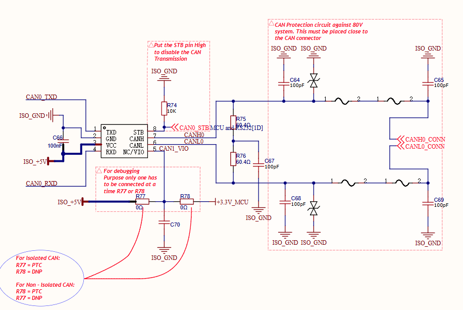
Pasted image.png

Failure symptom
The device was operating normally in the field, then CAN communication stopped permanently.

Our Analysis-

The failure is not intermittent. Replacing the transceiver restores communication. The damaged IC placed on a known-good board still fails.

Voltage Measurements on the Good Board & RCA board (powered, no bus connected)

Pin to GND

Good Board

Not good Board (RCA board)

VCC

4.89 V

4.89 V

VIO

3.29 V

3.29 V

STB

~0.01–0.08 V

0.083 V

TXD

3.28 V

3.29 V

RXD

3.29 V

3.29 V

CANH

2.38 V

0 V

CANL

2.38 V

0 V

Impedance of loose ICs (Measurements done using DMM)

(Damaged IC: Damaged IC of the RCA board; Good IC: IC of a working board; New IC: Tested the new IC to verify results of Good IC)

Pins

Damaged IC

Good IC

New IC

GND–VCC

2.86 MΩ

OL

OL

GND–VIO

3.29 MΩ

3.24 MΩ

3.28 MΩ

GND–STB/TXD/RXD

OL

OL

OL

GND–CANH/CANL

5.65 MΩ

5.46 MΩ

2.46 MΩ


Pins

Damaged IC

Good IC

New IC

VCC–VIO

4.14 MΩ

OL

OL

VCC–STB/TXD/RXD

~4.2 MΩ

OL

OL

VCC–CANH/CANL

3.11 MΩ

OL

OL

Reproduction attempts (all on 23S LFP, through our protection circuit)

Transient Test:

  1. Battery+ transients to CANH and to CANL, 100× each, device powered. No damage.

Shorting Battery+ Test:

  1. Battery+ shorted to CANH and to CANL, 1 h each, device [powered]. Afterwards the IC still worked. 

Observation after shorting for 1 hr. :-

After the test we desoldered the IC, then we measured the impedance across the CAN IC pins with respect to VCC. It showed a signature similar to the field failure: 

Impedance Between

Individual IC(Before Test)

Individual IC(After Test)

VCC-VIO

OL

4.1MΩ

VCC-STB

OL

4.0MΩ

VCC-TXD

OL

4.24MΩ

VCC-RXD

OL

3.96MΩ

VCC-CANH

OL

3.12MΩ

VCC-CANL

OL

3.10MΩ

* It returned to OL after 2–3 hours of rest.

Based on the observations and measurements above, what failure mechanisms could cause this damage pattern, even though the external protection circuit was unaffected? 

Thanks & Best regards,

Jiahui

  • HI Jiahui,

    First, please always recommend the A-version (TCAN1044A-Q1) with a more robust ESD specification.

    While the short voltage itself do not cause damage, if any inductive kickback and / or communication while the short is occurring, there may be voltage spikes that exceed the absolute maximum. With a common-mode choke populated for example (not shown) or additional inductance on the bus, instantaneous change in current during CAN communication can cause inductive kickback, and cause voltage transients ≥ 58 V (even if below the ESD's threshold). Hence, dependent on such an environment, the potential for exceeding the absolute maximum rating of the CANH and CANL pins.


    If the device is damaged, this is most likely due to exceeding the abs max ratings. I.e., with 48 V short to battery applied, the IC can observe transients greater than 48 V due to the overall inductance from the components used on the bus. If the transients are then greater than the abs max rating of 58 V, damage is common. This can be confirmed by measuring the voltage observed on the device pin when the 48 V short is applied (with and without the CMC, TVS etc.). 

    Also note that undamaged external bus protection does not rule out electrical over-stress (EOS). It only rules out EOS that exceeded the TVS clamp energy. The failure modes that fit "protection intact, transceiver dead, not reproducible in lab" typically fall into three groups: supply-side overshoot, logic-side / ground-shift over-stress, and bus-side stress that the protection passed through rather than absorbed.

    Hence, exceeding any absolute maximum rating may cause permanent damage and may see the below mechanisms, thanks.

    # Mechanism Limit violated Why protection stays intact
    1 VCC overshoot from the LM5013 rail (startup / hot-plug transient, load dump propagating through the 48 V→5 V stage, inductive ringing on ISO_+5V) VCC/VIO abs max −0.3 to 6 V Stress never reaches the bus-side TVS
    2 Ground potential shift between ISO_GND and MCU ground, injected through STB / TXD / RXD / VIO Logic input and RXD voltage −0.3 to 6 V; RXD current −8 to 8 mA  Entirely on the logic side of the isolation barrier
    3 RXD-pin overstress / RXD-to-GND damage — previously attributed to EOS when abs-max or ESD specs were exceeded RXD current / voltage limits MCU-side event
    4 TVS conducts during clamping — the diode should be rated to trigger below the 58 V, if not the IC can fail while the diode survives (Protecting CAN Interfaces Against ESD) CANH/CANL −58 to 58 V; differential ±45 V  The TVS operates within its own rating; the IC absorbs the overshoot
    5 Field ESD at the connector, where CAN cabling can accumulate discharges up to 30 kV capable of permanently damaging transceivers ESD rating Fast edge couples past series elements and the 100 pF caps before the TVS fully turns on
    6 Thermal/junction overstress from a sustained fault condition TJ −40 to 150°C  No bus-side damage

    Best Regards,

    Michael.