Part Number: TUSB211A
Hi TI team,
I am designing a USB 2.0 high-speed host port and want to confirm how the cable length figures in the datasheet should be read.
System topology:
SoC (USB 2.0 PHY) -> PCB trace [1.27cm] -> B2B connector -> custom cable [10 cm, 28AWG] -> small PCB with Type-C receptacle -> external cable (3 to 5 m) -> camera (USB device)
I plan to place the redriver on the small Type-C PCB, close to the receptacle. The SoC is the host, so the compliance target is the near-end eye mask at the Type-C receptacle.
What I read in the datasheet:
1. The features list says the device supports up to 5 m cable length.
2. The device comparison table lists cable length compensation for the near-end eye mask as "6/3 - 28AWG (10 - 24AWG with one redriver on each end)", described as pre-channel before the redriver / post-channel after the redriver.
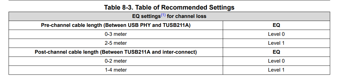
3. Table 8-3 (Recommended Settings) gives starting values for different cable lengths.
Questions:
1. Does "supports up to 5 m cable length" refer to the pre-channel only, the post-channel only, or the total pre-channel plus post-channel length?
2. Is the pre/post-channel limit a shared loss budget, or are the limits independent? For example, can I use 3 m pre-channel and 4 m post-channel (7 m total), or must the total stay within 5 m?
3. In my topology, the 3 to 5 m external cable falls on the post-channel side of the redriver, since the redriver is at the Type-C port. Is that supported for near-end eye mask compliance, or should the redriver be placed elsewhere (closer to the SoC or midway)? Would you recommend a second redriver at the camera end for the 5 m case?
Thanks
Manikandan R