TUSB211A: Cable Compensation

Part Number: TUSB211A
Other Parts Discussed in Thread: TUSB216

Hi TI team,

I am designing a USB 2.0 high-speed host port and want to confirm how the cable length figures in the datasheet should be read.

System topology:
SoC (USB 2.0 PHY) -> PCB trace [1.27cm] -> B2B connector -> custom cable [10 cm, 28AWG] -> small PCB with Type-C receptacle -> external cable (3 to 5 m) -> camera (USB device)

I plan to place the redriver on the small Type-C PCB, close to the receptacle. The SoC is the host, so the compliance target is the near-end eye mask at the Type-C receptacle.

What I read in the datasheet:
1. The features list says the device supports up to 5 m cable length.
2. The device comparison table lists cable length compensation for the near-end eye mask as "6/3 - 28AWG (10 - 24AWG with one redriver on each end)", described as pre-channel before the redriver / post-channel after the redriver.
3. Table 8-3 (Recommended Settings) gives starting values for different cable lengths.

Questions:
1. Does "supports up to 5 m cable length" refer to the pre-channel only, the post-channel only, or the total pre-channel plus post-channel length?
2. Is the pre/post-channel limit a shared loss budget, or are the limits independent? For example, can I use 3 m pre-channel and 4 m post-channel (7 m total), or must the total stay within 5 m?
3. In my topology, the 3 to 5 m external cable falls on the post-channel side of the redriver, since the redriver is at the Type-C port. Is that supported for near-end eye mask compliance, or should the redriver be placed elsewhere (closer to the SoC or midway)? Would you recommend a second redriver at the camera end for the 5 m case?

Thanks
Manikandan R
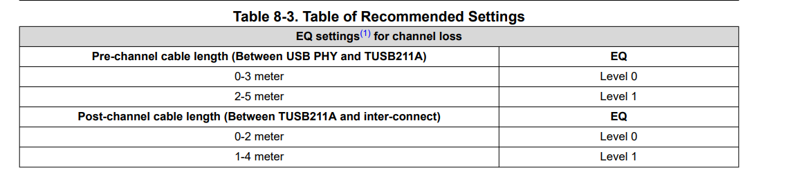
image.png

  • Hi Manikandan,

    1. Does "supports up to 5 m cable length" refer to the pre-channel only, the post-channel only, or the total pre-channel plus post-channel length?

    This typically depends on the location of the redriver. For example, on a system with a shorter pre-channel(0-0.5 meters), our redriver would be able to ensure a 5M USB2 cable could be used in the post-channel.

    Typically, it's best to look at it as pre-channel plus post-channel.

    2. Is the pre/post-channel limit a shared loss budget, or are the limits independent? For example, can I use 3 m pre-channel and 4 m post-channel (7 m total), or must the total stay within 5 m?

    With our redriver, the USB2 cable length should be able to support a bit more than 5 meters. At max setting, our redriver should allow the signal to support a length greater than 5 meters, at least 6 meters. 

    I would recommend trying to keep the pre-channel as low as possible, that way the signal is as strong as possible as it enters the cable in the post-channel.

    3. In my topology, the 3 to 5 m external cable falls on the post-channel side of the redriver, since the redriver is at the Type-C port. Is that supported for near-end eye mask compliance, or should the redriver be placed elsewhere (closer to the SoC or midway)? Would you recommend a second redriver at the camera end for the 5 m case?

    That would be supported for near-end eye mask testing, yes.

    For near-end eye mask testing, you would test at the type-C port with the redriver enabled to ensure the signal is not being over-compensated while still being strong enough for a 5 meter connection at the cable.

    For measuring the signal at the camera, you would use the far-end eye mask.

    If a 5 meter cable is being used, if you wanted to be safe, it would be best to use another redriver at the camera end, yes. That way, you can ensure the signal reaching the camera or being output by the camera can be received at either end of the connection.

    Thanks,

    Ryan

  • Hi Ryan,

    Thanks for all your inputs.


    The cable compensation parameters are in higher numbers for TUSB211A  in TUSB216 datasheet pg.no:2 .

    I'm not sure which to consider.Can you provide your thoughts.

    Thanks
    Manikandan Ramasamy

  • Hi Manikandan,

    The cable compensation parameters are in higher numbers for TUSB211A  in TUSB216 datasheet pg.no:2 .

    This is because the TUSB216 and TUSB211A are roughly equivalent in terms of compensation. 

    I would still recommend following table 8-3 as a starting point, then depending on the eye diagram the settings can be increased as needed.

    Thanks,

    Ryan