


Other Parts Discussed in Thread: TFP410, AM3359
Hi,
We want to know what is the recommended way to connect the
data lines of TFP410.
We want to use TFP410(DVI) with the AM3359 processor.
And we are refering to the below BeagleBone schematics for the DVI connection.
http://beagleboardtoys.com/wiki/index.php?title=BeagleBone_DVI-D
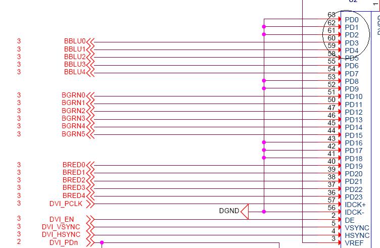
But the Data line (LCD_DATA[0..15]) connection is little bit confusing.
In the BeagleBone circuit diagram the Data lines are connected randomly as shown in the fig.
instead of LCD_DATA[0] to DATA 0 of TFP410
LCD_DATA[1] to DATA 1 of TFP410
LCD_DATA[2] to DATA 2 of TFP410
.
.
BBLU0,1...are LCD Data 0,1..
Could you please let me know what is the proper way to connect.
Regards.


