This thread has been locked.

If you have a related question, please click the "Ask a related question" button in the top right corner. The newly created question will be automatically linked to this question.

CAN bus

Other Parts Discussed in Thread: SN65HVD233, ISO1050, SN65HVD256, SN65HVD255

hi,

i need to design application based on 5V MCU that need to intreface with CAN bus.

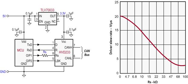
our customer uses SN65HVD233 to implement the CAN bus.

I need CAN bridge that can tolerate 5V supply and 5V UART connection to the MCU, and ofcuorse can connect to the SN65HVD233. 

please reccomend a CAN component to implement.

please send me a reference design for the CAN bus component.

  • While the HVD233 is a 3.3V device, its inputs allow for Vih to be 5.5V. Also the receiver output has a Voh-min of 2.4V which allows for a direct connection to a 5V controller. All you need is a low-cost LDO ,such as the TLV70033, that has a mximum input voltage range of up to 5.5V and provides a 3.3V, 200mA output with 2% accuracy. Then depending on your required slew-rate choose Rs and you are done.

    Hope this helps.                 Best regards, Thomas

  • hi,

    the current consumption of the 233 is 6mA? it is very low in compering to other p/n at this familly.

    if i can supply both 5V and 3.3V, wich is the best option for CAN bus component?

    if I need to implement at board that need FCC and ETSI certification, do u think using isolater device like ISO1050 will be better?

    can u send any application note with reference design or documment of how to implement fully the CAN bus at board including any apecial PCB requierrments?

  • Please look at the CAN EVM as a basic reference design for CAN circuits,  http://www.ti.com/tool/sn65hvd255devm. Are you trying to design your CAN & MCU with only 5V and then interface on the CAN bus to a 3.3V CAN or do you want to use the 3.3V CAN and level shift between them?    CAN bus is differential and 5V and 3.3V CAN are interoperable as the recessive and dominant (differential) signals are the same.  For 5V CAN we just released the SN65HVD255 and a sister device SN65HVD256 with RXD level shifting.  The 3.3V CANs are the SN65HVD23x parts already referenced.     Moving to ISO1050 you get isolation which will help if you have large ground shifts or need isolation due to safety ratings at the system level.  In that case you then have an isolated GND and power supply for the CAN network, away from the rest of the system. 

    We also have several applicaiton notes on CAN that describe the network.  Another tool you can use to find info is www.ti.com/CAN

    -- Scott

  • hi,

    I will use a 3.3V MCU , and the 65HVD233.

    in compering to the other CAN components, is it the best choise?

    at the spec its current consumption is 5mA, and the high level output current is 50mA. what is the max current consumption during transmit?

    are there any special PCB trace line requierments for these components?

  • The HVD233 is a good choice to use with the 3.3V MCU. It keeps the design to a single supply and lowers the power used by the CAN transceiver vs a 5V supplied CAN.  The HVD233 is in the latest 3.3V CAN generation along with the HVD234 and 5.  It is really a choice for you and your applicaiton which of these have the features and modes that match how you will use the device.  

    The normal max during transmit will be 6mA in the CAN transicever plus the current needed to drive your system load dominant.  Under a normal CAN bus load the actual current during dominant will be approxiamtely the 50mA listed which is what is needed to get the differential voltage across the normal R load (2x termination resistors of bus in parallel  + all the other nodes in parallel).  Recessive is the lower 6mA max ICC  (the device itself during dominant also only needs 6mA, but the rest will flow through the device into the load on the bus).  The ABS max output of the CAN driver is +/-250 mA per line Ios in the Driver electrical char section of the DS.  This is the level to which the device will current limit the outputs when driving against a short to either a supply or GND if the bus is shorted. 

    For PCB recommendations you can refer to the SN65HVD255 CAN EVM, http://www.ti.com/tool/sn65hvd255devm  , which is also a generic CAN EVM and could be used for the SN65HVD233.  The main points are to keep the bus pins symmetrical and at 120 ohm to match the cabling and avoid signal reflections.  I would recommend putting pads on the board for external protection & filtering if you are in a harsh environment, you can always leave them open if you don't need them, but if you find in the system you need them then it is easy to just populate them.

    - Scott

  • hi,

    please explain what are pins D (1) and R (4) - which is RX and TX ?

    at figure 28 D is CANTX , but its logic symbol at page 1 its input, means I connect TX line from MCU  to that pin so its recieve data from CAN point of view??

    same for R as it is RX from MUC?

  • For the HVD233 the pins are:

    Pin 1:  D (Data) = TXD = input from MCU to CAN transceiver to TRANSMIT DATA -- this is the pin that puts will translate digital data to the CAN bus (driver)

    Pin 4:  R (Receiver) = RXD = output from CAN transceiver to MCU RXD input -- this is ouptut of the RECEIVED DATA on the bus lines. 

    The functional block diagrams on page help with clarification of which pin is connected to which function inside the transceiver.

    -- Scott

  • hi,

    "The functional block diagrams on page " - which page?

    do i need pull up resistors for the UART  line connection between the CAN and the MCU?

  • Functional Block diagrams page 1.

    Pull ups -- depends on your UART/MCU.  If it is push/pull IO you likely wouldn't need a pull up as it should adequately drive the inputs including timing.  If the MCU is open drain outputs you will definately need pull up on the D input to make sure that the CAN timing you want will be acheived. 

    -- Scott

  • hi,

    at the EVM schematics:

    1. does D1,D2 need to be TVS or 2 oposites reguler zener - which do u reccomend? if either TVS or ZENER  can u reccomend on specific component or parameters(voltage, allowed capacitance etc...)

    2. what is the approximate value range of C2 and C7?

  • hi,

    few questions:

    regarding table 3 and 4 at the EVM data sheet, i will use the standerd terminaion, with option for comom mode chock, TVS and filter capacitors (like C2,C7).

    can u reccomend on TVS value or p/n?

    the current of the CMC need to be no more then 250mA?

    at what resonant frequency range of the CMC and capacitors might defect the data line relaiability?


  • 1) D1/2 should be TVS or you could use varistors as a functional alternative. Examples are SM712 or MMBZ TVS.  Use the lowest working voltage possible to make sure the TVS or varistor clamping voltage is below the abs max of the CAN transceiver.  Also, lowest capacitance solutions are best.

    2)  C2/7 -- depends on a specific frequency range filter you are trying to acheive based on noise issues.  They normally are not needed at all.  Typical range is up to 100pF.

    CM choke current:  yes should be 250mA to match the IOS short circuit current limiting the the HVD23x.

    CM choke / caps and signal integrity - that is the possible down side of using them.  If you have a specific or general RF emissions or immunity challenge they can be tuned to help, but they may also be a resonant circuit at other frequencies and make it worse.  It really depends if you need them or not for the applicaiton, network, noise challenges......   The good news is CM chokes for CAN are widely avaible from about 11uH to 470uH but most widly used is none through about 100uH and the caps could be from none to about 100pF so there is a wide range of flexibility and trade off in system design all on the same footprints.

    -- Scott


    -- Scott