This thread has been locked.

If you have a related question, please click the "Ask a related question" button in the top right corner. The newly created question will be automatically linked to this question.

DP83848C phy autonegotiation and link issues

Other Parts Discussed in Thread: DP83848C

Hi,

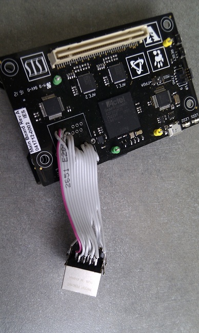
We are trying to build a sensor platform using the DP83848C physical layer ethernet interface. We took the SmartFusion Evaluation Kit from Microsemi (http://www.actel.com/products/hardware/devkits_boards/smartfusion_eval.aspx) as our reference design, and built our board basically copying the relevant parts from their schematic, the only difference being the RJ-45 connector. We've found that our boards fail at the autonegotiation step, no link is established.

Here is what we have tried so far:

1. We've made sure that supply voltage and 50 MHz clock are present, device is not powered down (pin 7), and is not reseting (pin 29). 

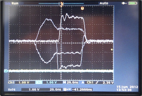
2. With autonegotiation and Auto-MDIX turned on we've measured the signals on both the TD and RD pins, and verified that normal link pulses (NLP as defined in the autonegotiation specification)  are present. We've found however that the signals look unlike the ones seen in Application Note 1519 DP83848.

3. If connected to an ethernet hub our device was not able to successfully autonegotiate, even though the ethernet hub was sending fast link pulse bursts with the acknowledge bit on, meaning that it had correctly received the link code word from our device.

4. We've assumed that the inability of our device detecting link code words from the hub, and the difference in pulse shapes are due to the different RJ-45 connector (J0G-0007NL as opposed to . Unfortunately they were not pin compatible, so we've used a 2 inch long ribbon cable to connect to the PCB. 

The pulse shapes were still different, our device was still unable to detect link code words. In the picture the longer signals are the differential signals measured on the working evaluation kit, the shorter signals with the higher amplitudes are the differential signals we have measured on our board.


5. We've checked our software as well, we start out with a reset (bit 15 in BMCR), then we wait more than 3 us and  enable autonegotiation (bit 12), restart autonegotiation  (bit 9), and enable collision test (bit 7) with one write to BMCR.

Any ideas what else we could/should check?

Our design is open-source ( http://code.google.com/p/marmote/source/browse/#svn%2Ftrunk ) the schematics of the board can be found here: http://code.google.com/p/marmote/source/browse/trunk/hardware/MainBoard_RevA/MainBoard_RevA_Sch.pdf (click "View raw file" to download pdf).

Thanks,

Benjamin

  • Benjamin,

    The width of the incorrect link pulse appears to be half that of a standard link pulse.  That could occur if the device were configured for MII mode, but provided with a 50MHz reference clock.  Could you check the RBR register to confirm the RMII setting?

    The incorrect link pulse also appears to have a higher than expected amplitude.  Please measure the values of the 49.9 Ohm termination resistors and the 4.87 kOhm RBIAS resistor when the board is powered down.  A stuff error in these resistors could impact the link pulse amplitude.  Please also measure the voltage across the RBIAS resistor to ground when the board is powered up.  It should measure ~1.2V. 

    Patrick

  • Patrick,

    Thanks for the quick answer. Following your instructions we've found that, due to a part number error in the BOM file, RBIAS is actually populated with a 4.87 Ohm resistor instead of a 4.87 kOhm one. We'll get back with the results once this component has been replaced.

    Meanwhile, could you please let us know if the J0G-0007NL RJ-45 connector is compatible with the DP83848C PHY IC? The J0011D21B, found in our reference design (SmartFusion EVAL-KIT), uses a different magnetics topology and we are wondering if that can also be a possible issue.

    Thanks,

    Sandor

  • Sandor,

    The electrical specifications for the JOG-007NL RJ-45 connector are roughly comparable with those of the J011D21B RJ-45 connector.  The return loss specifications are slightly different, but in and of themselves, I would not expect that to be a problem. 

    I have several concerns with the topology:

    1. First and foremost, the series chokes are on the device / PCB side of the transformer.  We recommend having the series chokes on the cable / line side of the transformer.  We do not want anything to impede or perturb the signals between the DP83848 and the transformer. 
    2. I also have concerns related to the TCT connection (pin 12).  The TCT center tap is connected via the series choke.  This will impede the ability of the DP83848 to draw current from the center tap. 
    3. Since the RCT center tap is connected directly (i.e. not via the series choke), the TCT center tap connection also represents an asymmetry between the TD+/- and RD+/- paths.  For applications using Auto-MDIX, we recommend that these paths are as symmetric as possible so that the functionality is comparable when Auto-MDIX resolves to an MDI (straight) or MDIX (crossed) configuration. 

    It is quite likely that these characteristics of the JOG-007NL RJ-45 connector will have an adverse effect on the functionality of the DP83848.

    Patrick

  • can you please provide another link for  Application Note 1519 DP83848 ,this one is not working...

  • Thank you for bringing this to our attention.  This application note was recently revised to improve the format.  Apparently the link was updated, but that update was not reflected in the E2E post. 

    I have edited the links in the posts so that they are now current.  Hopefully that will prevent confusion in the future.

    Patrick