


I have a customer that is having an issue with a design that was developed by another engineer (long since retired) and the design has been spread throughout the company over the years. It has finally come to light that there are issues with this design and it affects some of the largest customers in the world. Any insight would be appreciated (even if the answer is, this is wrong and needs to be changed).
Here are some current questions from the assigned engineer:
Pleas find attached:
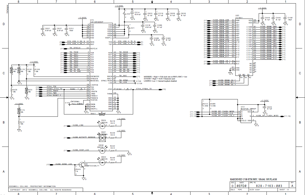
1. 828-7166-002 - (1 page) schematic for EFB system that works. We were troubleshooting with you this design sometime ago.
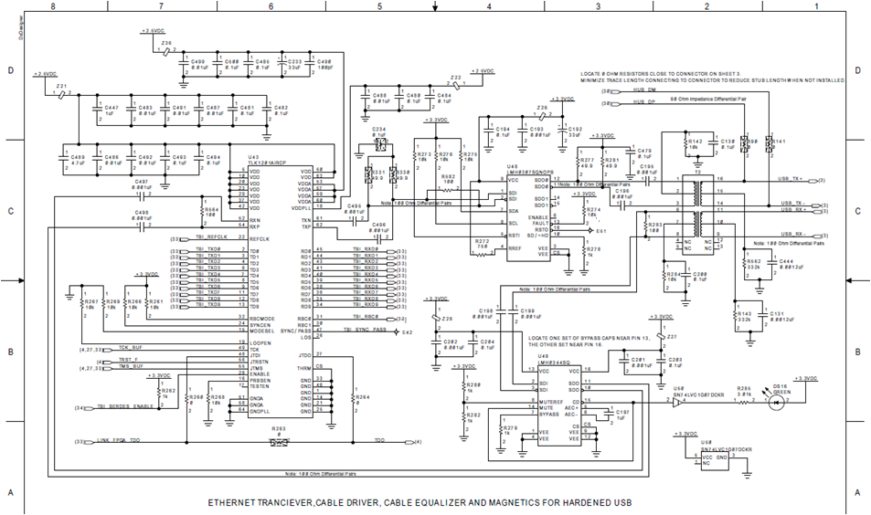
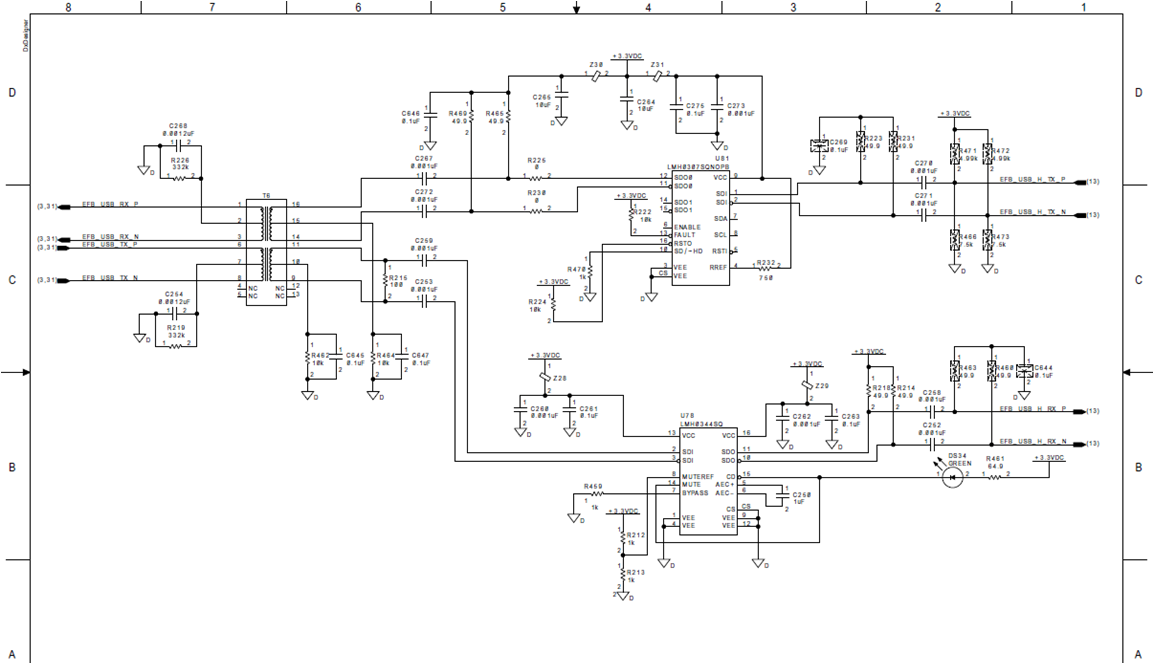
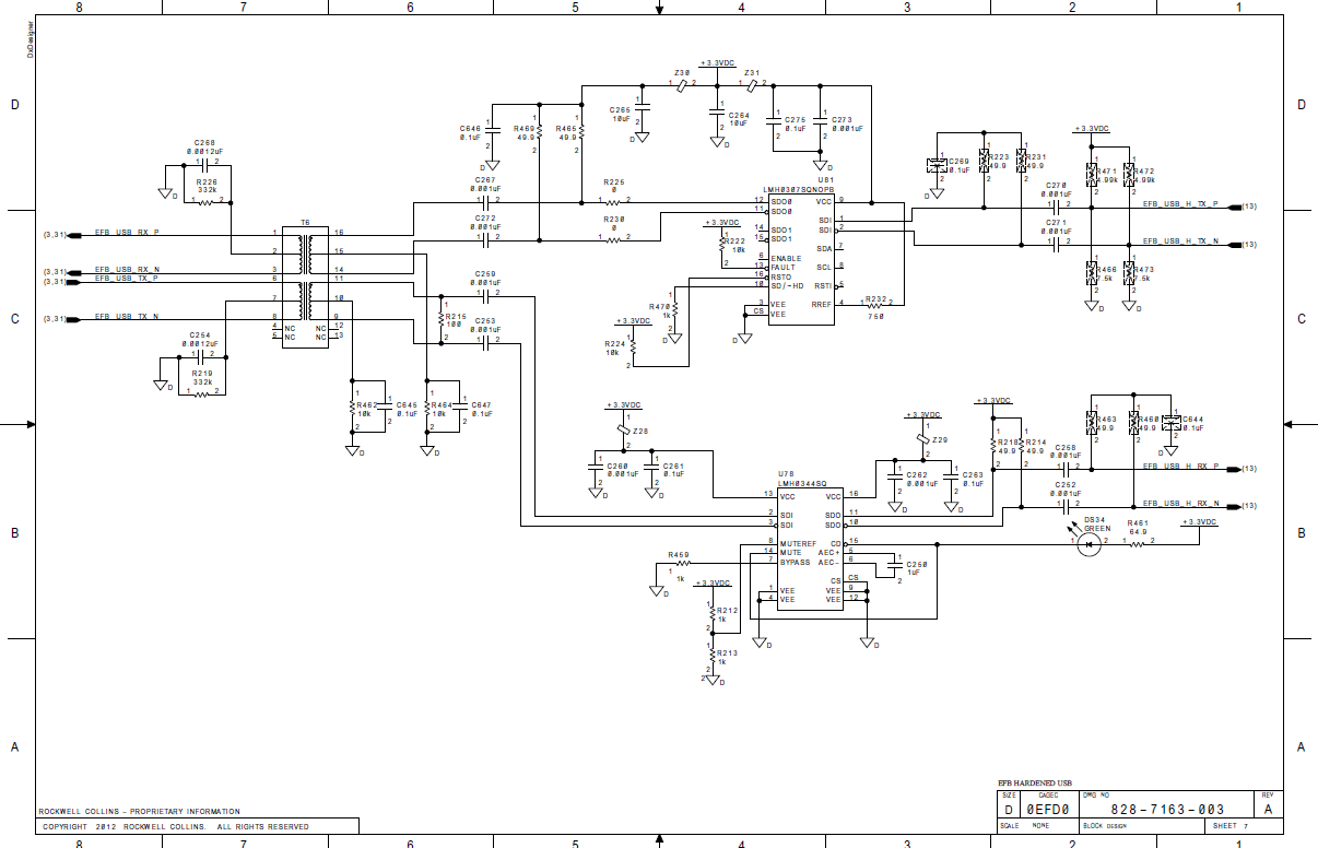
2. 828-7163-003 - (2 pages) schematic that has questioned LMH components termination network.

Please also let me know how critical is the serial DC blocking capacitor value (currently 0.001uF) for the serial data link to work reliably.
There is a question about I/O pull-up termination on LMH0307 and LMH0344.
Please let me know what shall be absolutely terminated? The data sheet is kind of controversial.
Other feedback from our recent lab sessions:
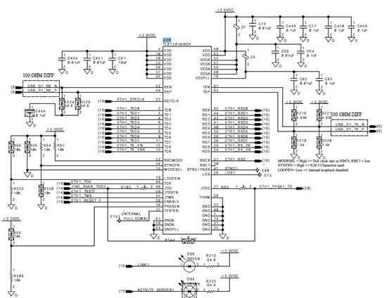
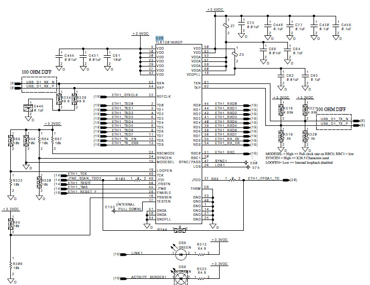
I would like to share with some findings in regards to the corrupted serial data out of TLK1201issue.
What was analyzed:
1. serial TX link (pins 61,62) , marked as RX data on image
2. serial RX link (pins 52, 54), marked as TX data on image
3. parallel TX data
4. parallel RX data
Found:
1. serial TD data (out-yellow) does not correspond with serial RX data (in-green) - see image attached 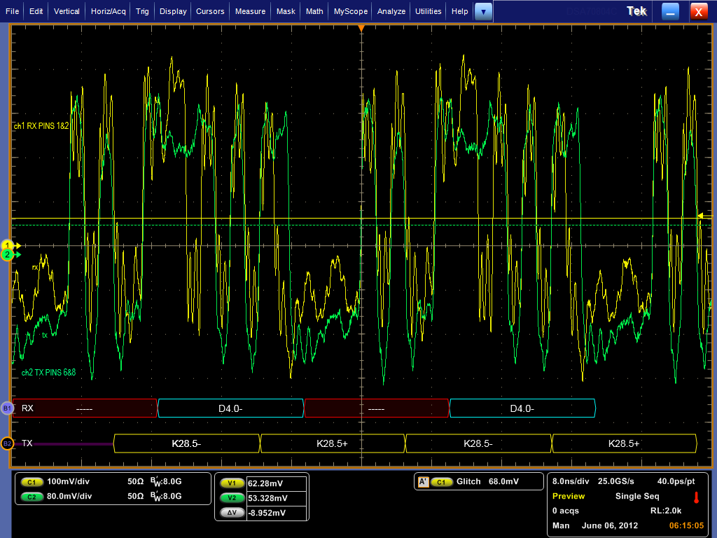
2. parallel RD data matches with parallel TX data:
RD0-RD9 = 0011111010
TD0-TD9 = 0011111010
Please let me know what could cause the serial data to get corrupted.
I will try to have a look at the noise level at VDDPLL (pin18) for the power supply and SSN noise levels.
What has to be a roll-off frequency for the low pass filter at the VDDPLL pin? 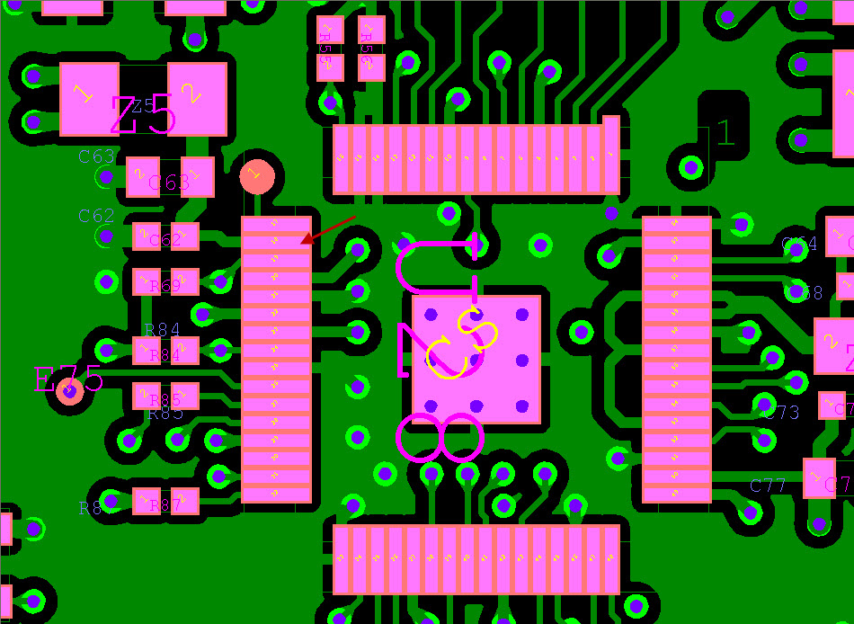
Attached:
1. schematic page with TLK 1201
2. serial TX/RX data scope screen image
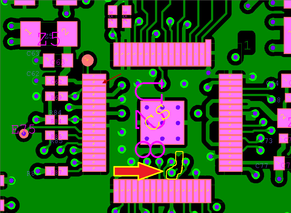
3. pcb layout around VDDPLL pin
4. Z21 (see schematic) data sheet link - http://elcodis.com/parts/4406679/CZB2BFTTD600P.html#datasheet
I will try to get the schematics and images uploaded.
Basically, they have added a XFMR for lightning protection and it appears to have not been properly terminated. To add insult to injury they are now trying to increase the data rate of the design (and it has failed miserably).
Joe

