This thread has been locked.

If you have a related question, please click the "Ask a related question" button in the top right corner. The newly created question will be automatically linked to this question.

XIO2001 PCI bridge reorganization issue

Other Parts Discussed in Thread: XIO2001

Hello, all.


Now I am trial testing XIO2001 on our original chipset, which configuration is detailed as below;


CPU <=> PCIe ver.2.0 (2.5Gbps transmission) <=> XIO2001 <=> PCI ver2.2 <=> PCI slot


Then the PCI bridge could not be recognized on CPU on startup sequence.


My concernment is whether XIO2001 could support PCIe ver.2.0 (2.5Gbps transmission) from Host.


If supported, please let me which hardware configuration(rayout) should be taken in consideration.


Thank you in advance for your information.


Best regards.

  • Hello,

    We are looking at your question and we'll reply soon.

    Regards.

  • Hello,

    The XIO2001 does support PCIe 2.0 Gen I (2.5 Gbps)

    Can you send your schematics and a PCI register dump of the XIO2201? What is the PCI downstream device? Are you following the Power-up sequence described on the XIO2001's datasheet?

    Regards.

  • Hello, thank you for your prompt reply.

    Regarding your inquiries, please see my comment as below;

    Now I am contacting to TI local office to transfer schematic properly to you, due to security reason.

    Then the person in charge has already done.

    On our configuration, EEPROM is removed, since your EVM could operate even if removing this.

    Also, please let me clarify about the PCI resistor dump, since we don’t send any command to XIO2001PNP.

    PCI downstream device is not used, the PCIe 2.5Gpbs is directly input from HOST CPU into XIO2001PNP.

    We are following your power-up sequence, as a result the waveform on starting this device is same as the figure on the datasheet.

    Thank you in advance for your information.

    Best regards,

  • Hello,

    I have reviewed the schematic and it looks correct.

    What Operating System are you using? Can you check the PCIE_CLK signals?

    Verify the correct placement of the PCIE_TX AC coupling capacitors, the value must be 0.1uF

    Regards.

  • Hello. Thank you for your continuous support.


    Regarding your additional inquiries, please see my comment as below;


    The OS what we are using is Windows7.


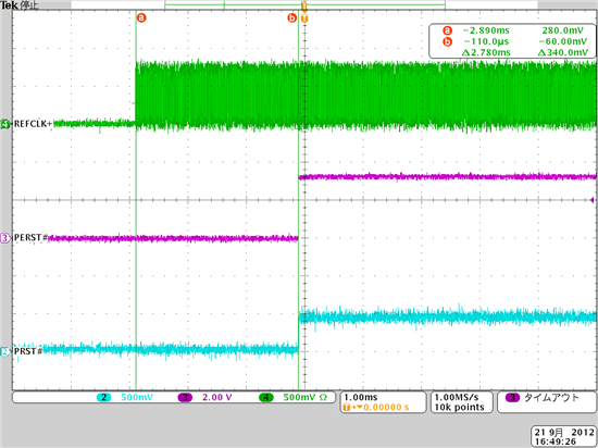
    The waveform of PCIE_CLK on starting up is below;


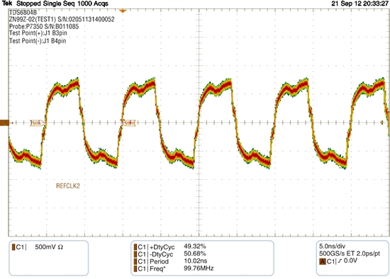
    The normal operating waveform is as below;


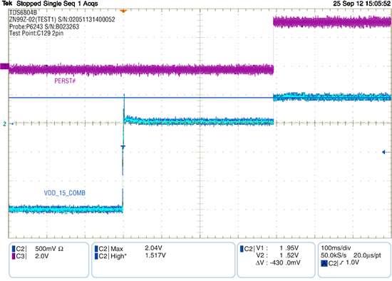
    But we found some abnormal waveform on the voltage on VDD_15_COM pin,

    The voltage after power on is 1.5V, but it increase to 2V after PERST# rised.


    Meanwhile, please let me clarify ones again, whether it is allowed for us not to use external EEPROM on our board, as you can see NOMOUNT comment on this place of our schematic.


    Thank you in advance for your information.


    Best regards,

  • Hello,

    your waveforms looks good, regarding the VDD15_COMBIO make sure your VDD15, VDD33 and VDDA are within limits.

    The external EEPROM is optional to set some special features and to customize some IDs, the bridge can work without external EEPROM, however if the external EEPROM is not implemented, then the BIOS has to configure the registers that are loadable from the eeprom.

    These registers are described on Table 3-8 of the XIO2001's datasheet. There is also an implementation note on Section 7.2 of the XIO2001 Implementation Guide.

    Regards.

  • Hello. Thank you for your continuous support.


    Regarding VDD15_COMBIO, I check the waveform on VDD15, VDD33 and VDDA, the waveform on each pins are within limits.

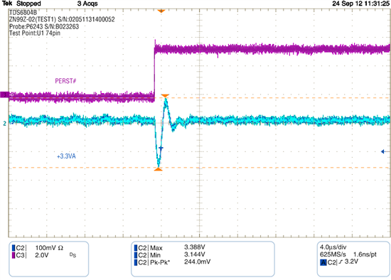
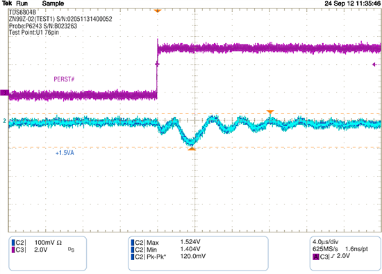
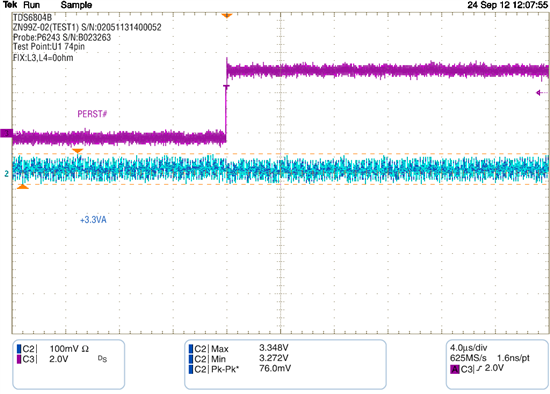
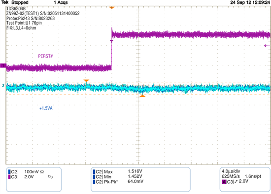
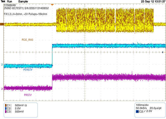
    However on starting up sequence, the +3.3VA(which connects to VDD_33_MAIN and VDD_33_REF_CLK) and +1.5VA(which connects to VDD_15_MAIN, VDD_15_PCIE, VDDA_15_PCIE_RX, VDDA_15_PCIE_TX and VDDPLL_15_PCIE) are unstable, as you can see each waveforms below;


    This phenomenon was resolved after removing the inductors L3 (between +1.5V and +1.5VA) and L4 (between +3.3V and +3.3VA).


    Should we remove these inductors?


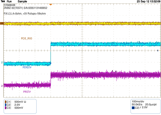
    Meanwhile, I could found out other abnormal phenomenon on TXN and TXP pins on XIO2001PNO after rising PERST#.

    On some cases, signal was output on these pins, but some cases not.

    Neither output this signal nor not, the PCI bridge itself is not recognized on HOST CPU.


    If you need to know more detail on each phenomenon, please inform me to have further proceed.


    Best regards,

  • Hello,

    Per specification both the PCIE Rx and Tx diff pairs should be AC coupled, the standard is to populate the AC coupling caps on the TX lines of each devices, in this way you will have always AC coupling caps in both TX and RX lines ( ones on the devices side and the other ones on the host side).

    In your schematic I don't see the AC caps on the host side, i.e. the AC caps that should connect with the PCIE_RX terminals of the XIO2001, can you check that? also the value is critical, they must be 0.1uF

    Are you getting a warning or yellow bang on windows? Can you send a screenshot? Also, make sure the resistance between REF0_PCIE and REF1_PCIE is the correct value.

    Regards.

  • Hello. Thank you for your reply.

    I tried to replace another IC(XIO2001PNP) on our board, then the operation was successfully done.

    I judged that this issue was caused by some defect on the device itself, therefore this issue is closed.

    Thank you again for your support.

    Best regards,


  • Hello. Thank you for your support.


    I have one question on your previous comment.


    > The external EEPROM is optional to set some special features and to customize some IDs, the bridge can work

    > without external EEPROM, however if the external EEPROM is not implemented, then the BIOS has to

    > configure the registers that are loadable from the eeprom.


    Currently, we don't either place EEPROM on our board or send any command from BIOS, but the operation is going fine.

    Do you have some mandatory resistors which shold be set from BIOS in XIO2001PNP in order to avoid some risks?

    Thank you in advance for your reply.

    Best regards,

  • Not mandatory,

    The bridge has basic functionality without special configuration, the custom configuration through either external EEPROM or BIOS is for special features, you can see the EEPROM Register Loading Map to see which registers can be configured and what features do they manage.

    Regards.

  • Hello,

    I got CPCN information on XIO2001, which describes that EXT_ARB_EN and CLKRUN_EN need to have additional register which pulls the signal either high or low.

    On our design, both pins are pulled down by 10kohm register.

    (This is based on the schematic which is sent to you on Sep 28th 2012.)

    Please let us confirm whether this method is sufficient on this matter.

    We thank you once again for your information.

    Best regards,

  • Hello,

    Your design is correct, a 10k pull-down on those pins is OK.

    Regards.