This thread has been locked.

If you have a related question, please click the "Ask a related question" button in the top right corner. The newly created question will be automatically linked to this question.

Unable to transmit from a DP83849C

Other Parts Discussed in Thread: DP83849C

I have a DP83849C interfaced with a C6745 RMII configuration.  I am trying a test case to transmit a UDP message with no data 100BaseTX, full duplex.  I can write/read the MDIO along with measuring the 50Mhz clock and I see the TX_EN_A along with the two data line toggling.  I have tried with and without auto negotiate.  The alive register on the C6745 reads 0xC0000000 so it sees phy addresses at 0x1E and 0x1F. The registers in the 8349 read as follows

3100, 7840, 2000, 5CA2, 01E1, 0000, 0004, 2001,  0000 14 times..., 0100, 0020, 0000, 001F, 0904, 0000, 0000, 6011

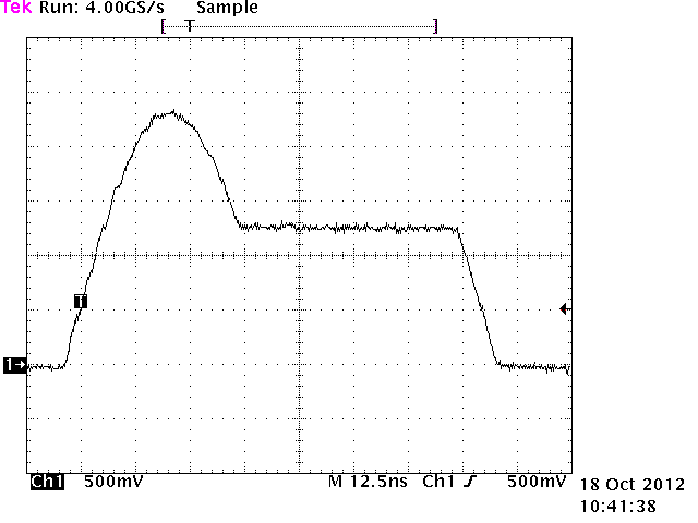
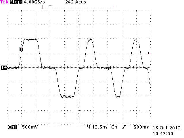
I do not see any data coming from the TPTDP/TPTDM lines.  What am I missing?  What do I need to receive a message?

Thanks, Gerry

  • Just like a PC, the C6745 RMII  needs ( the equivalent of ) a TCP/IP stack.  What settings have you used so far for setting it?  Did you initialize the lines between the two properly ( I admit i tend to forget port inits at times so this is one of the first i check ). Do you have TXD connecting to the  correct RXD lines?

    With respect to the DP83849c...

    http://www.ti.com/lit/ds/symlink/dp83849c.pdf

    Table 1. Auto-Negotiation Modes

    2.3 PHY Address - which setting did you use?

    1.2 MAC Data Interface - pins 12 and 50 clock reference. no short/open on the connections to interfere with the clock? ( sometimes the physical is the issue not the programming )

    page 36 -  center tap to Vdd with caps to ground for ( your part name of that page's ) T1?

    which mode and which address did you set it to?

    These and more questions can point you to getting it working,

  • Gerry,

    As discussed on the phone, I will provide some sample waveforms and suggested debug techniques.  First though, we should investigate the initial configuration of the device into RMII mode via the external straps.  The current thinking is that the strap is being pulled down despite an external pull and the device is initializing in MII mode.  The subsequent register write to configure RMII mode may not be successful due to the internal clocking associated with switching between MII mode and RMII mode.  If we can get the initialization into RMII mode via strap resolved, the transmit problems may go away.

    Patrick

    ----------------------------------------------------------------------

    Evaluate the signaling without a link.  For looking at output signaling, I generally use a short (1-2") pig-tail cable with 100 Ohm terminations.  With this cable plugged into the RJ-45 connector, the transmitter will be properly terminated and the voltage levels should be correct.  In this configuration, you can measure the transmit signaling.

    I have attached a picture of the terminated cable for reference:

    ----------------------------------------------------------------------

    Evaluate the signaling with the device linked to itself.  To allow the link to connect to itself, you will need to create an external loopback plug.  External loopback (also called "line loopback") can be used to loop the high speed lines of the link back to themselves.  The easiest way to achieve this is by making a custom cable and plugging it into the RJ45 connector.
      1. Cut a cable with about 1 foot of cable and the RJ45 connector
      2. Strip off about 3~4 inches of the outside plastic shield to expose the 4 pairs of twisted pair cable
      3. Bend back pairs 4/5 and 7/8 (these will not be used)
      4. Solder pair 1/2 to pair 3/6
            1. Solder wire 1 to wire 3
            2. Solder wire 2 to wire 6
      5. Now you have a loopback cable.
    Plug the cable into any operating 10/100 Ethernet port and link will be established (assuming Auto-Neg is enabled).  You can also force 100BASE-T or 10BASE-T full duplex to test those modes explicitly.  In this configuration, you can measure the transmit signaling.

    I have attached a picture of the loopback cable for reference:

    ----------------------------------------------------------------------

    Below are some representative signals that you can expect to see.

    Link pulses should be seen in 10M mode and in Auto-negotiation during link establishment.

    Scrambled idles should be seen when the device is forced to 100M or when 100M has resolved as a result of Auto-negotiation. 

    ----------------------------------------------------------------------