This thread has been locked.

If you have a related question, please click the "Ask a related question" button in the top right corner. The newly created question will be automatically linked to this question.

ISO35T driver line mortality

Other Parts Discussed in Thread: ISO35T

Dear all, 

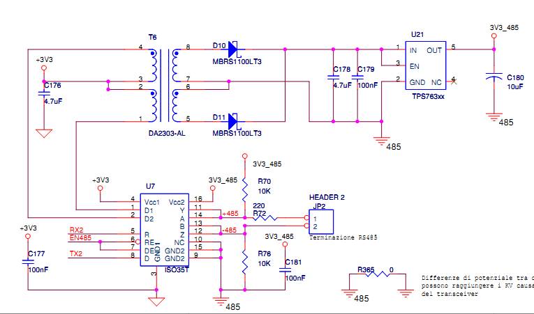
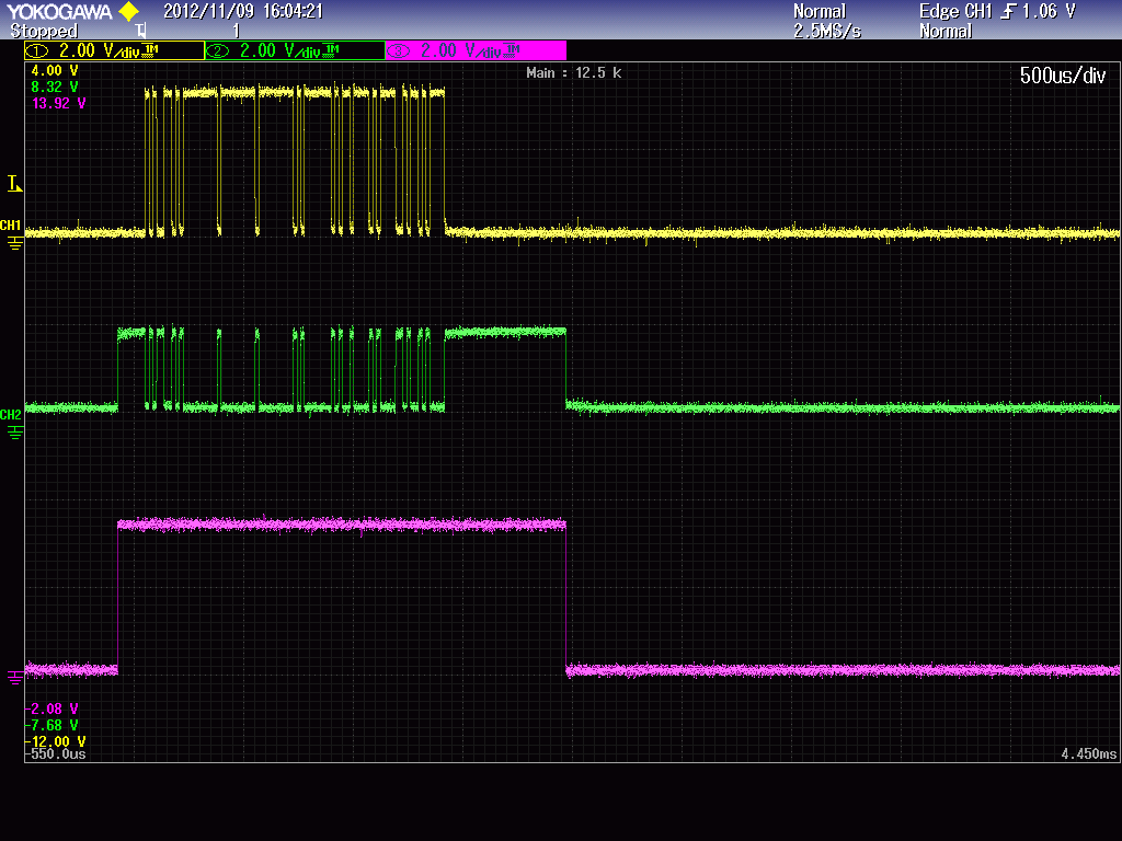
    I am experiencing a high death of the ISO35T driver line. I use the ISO35T in half duplex mode with the pin Y connected to a with a 10K pull-up (3.3V) and the pin B connected to Z with a 10K pull-down. Usually when the line is broken, I see that the Y-A line can not reach a high impedance state. I wonder whether it is a bad lot or there is some other problem. I checked the PCB and it looks fine. 

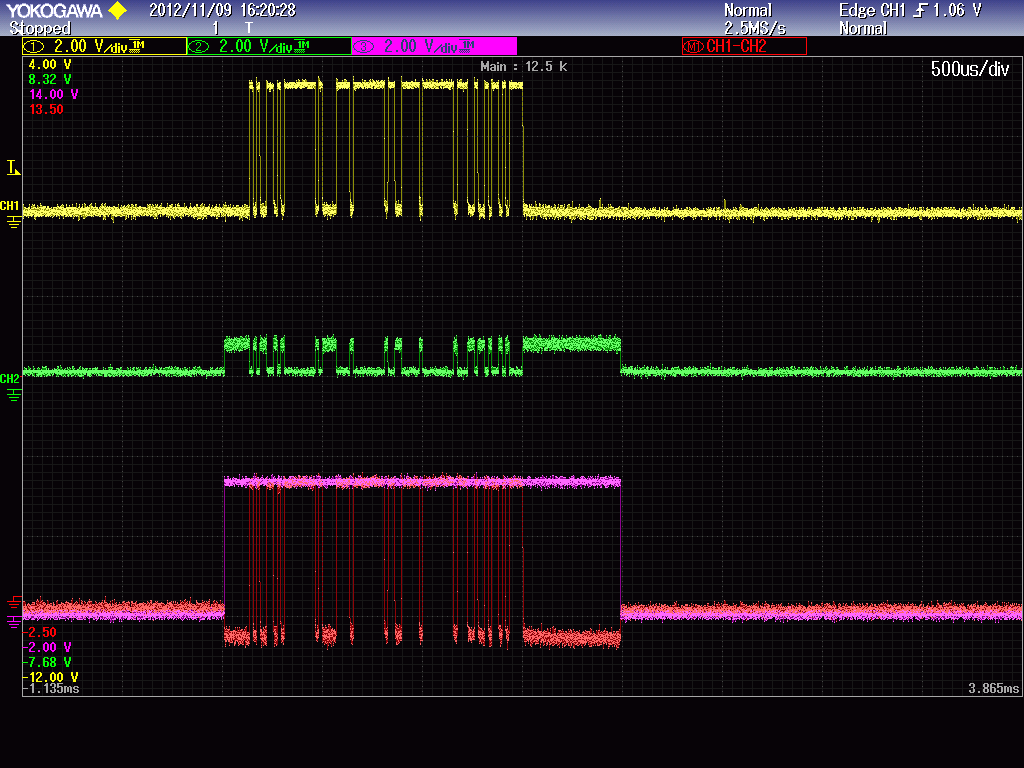
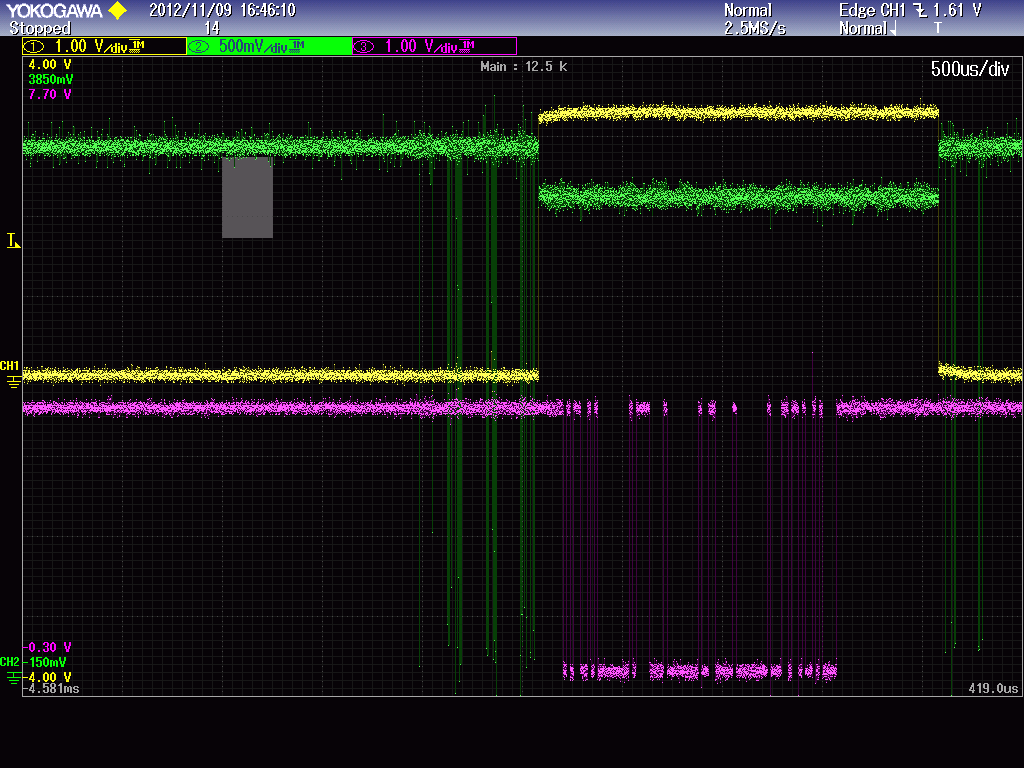
Another thing I notice is a small interference of the enable signal (pin 6-7) in the Rx (pin 5).

Thank you in advance

  • Hello Peregrinus,

    can you send a copy of your schematics to me at jfockler@ti.com?

    How are you enabling the driver and receiver?

    How is the line break occuring - are you manually disconnecting?

    Where is the pull-up on the Y-A line? Depending on where the pull-up resistor is placed you may not see Y-A go to the high-Z state, if for example it is close to the ISO35T and the pull-up in on the Vcc  side and you are measuring on the device side of the line break.


    Best Regards,

    Joe

    The small interference on the enable signal is normal.

  • Joe Fockler said:

    can you send a copy of your schematics to me at jfockler@ti.com?

    The signals +485 and -485 drive the line. In addition there are two 10uH series inductors in the line. These are an inheritance of a previous design. I find it odd and I think they have been placed for over current protection. I tried to remove them but the signal edges do not change meaningful. 

    How are you enabling the driver and receiver?

    The break seems to occour mainly with the master side. It polls a maximum of 4 slave devices. The Tx is enabled just before starting the communication and disabled immediatly after the end. There are not conflicts in the line. 

    How is the line break occuring - are you manually disconnecting?

    I have a connector in the line an the line is connected/disconnected manually. 

    Where is the pull-up on the Y-A line? Depending on where the pull-up resistor is placed you may not see Y-A go to the high-Z state, if for example it is close to the ISO35T and the pull-up in on the Vcc  side and you are measuring on the device side of the line break.

    The resistors are very close to the ISO35T and I measure the voltage on the ISO35T pins. When the line is not damaged I see the 3.3V signal range on the two lines, but often the range on the Y-A signal is only 1V. 

    Best regards.

  • Thank you, Mario. The schematic looks OK. I don't see any issues with the schematic as shown.

    Can you send some oscilloscope shots of the R, T, RE#/DE, Y and Z signals?

    Best Regards,

    Joe

  • Thank you Joe.

        It seems that the ISO35T is damaged when I hot plug the 485 interface. 

    In the first image I have the B-Z line in yellow, A-Y (green) and enable (pink). The A-Y has about a 2V range, when the ISO35T is healthy it shows 3.3V as the B-Z.

    After I hot plug the 485 the A-Y line is damaged and teh signal remains of 1Vpp even when I disconnect the cable.

    The device communicate with a second isolated ISO35T device an the isolated grounds of the two devices are connected.

      Here the DE (Y) and T(pink)  and the Rx (half scale green) signals:

    I wonder about the reason of the dead of the line when I hot-plug the interface.

    Thank you in advance

  • The ISO35T is not designed for hot-plug applications. Hot plugging can cause undesired internal biasing of circuits, thus creating unwanted return paths in the device.
    The second scope capture of the enable signal is an example of what can happen when the correct power-up sequence is violated by hot plugging

    Best Regards,

    Joe

  • Thank you Joe.

       According to the datasheet the lines are protected against over-voltages. I suppose the slave takes too current. 

    What is the correct power-up sequence? When I hot-plug the master is already powered. 

    In the second snapshot i put the difference signal A-B superimposed with the enable signal, but the enable looks fine.

    Is there something I can do to protect the IC against hot plug?

  • The correct sequence would be to have GND1 and GND2 potentials applied before applying Vcc1 and then Vcc2. So when unplugging the ISO35T or plugging it into a new board, the power lines must be energy free.

    Thank you, Thomas