This thread has been locked.

If you have a related question, please click the "Ask a related question" button in the top right corner. The newly created question will be automatically linked to this question.

TPD12S521 and HDMI connector chassis GND connections

Other Parts Discussed in Thread: TPD12S521

Hi all,

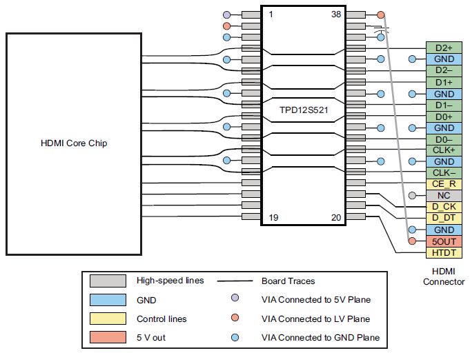
I will use TPD12S521 on my HDMI interface.

As all you know we usually connect shielded connectors (RJ45, USB...) chassis to GND by a ferrit bead, RC, or just RAnd the protection devices GND is connected to the connector chassis.

But most of the reference design, HDMI connector chassis had directly connected to the GND.

There is board layout guide on TPD12S521 datasheet but not mention about connector chassis.

What is your idea, should I constitute a TMDS GND plane and connect it to connector chassis, then tie this plane to GND with ferrite bead, or directly connect all of them to GND ?

Best Regards. 

  • Hello Yilmaz,

    When routing the GND for TPD12S521, the GND should be connected to Chassis GND. Establishing a seperate signal ground is a practice which helps remove ground loops on the TMDS lines. Since TMDS lines are fairly resistant to common mode noises (i.e. shifting reference plane voltages) this may or may not benefit your application, but it should not hurt it.  I do want to stress the importance of attaching the TPD12S521 GND to Chassis GND as this helps protect the HDMI Core Chip by isolating the Signal GND from ESD energies by dissipated by the Transient Voltage Suppressor (TVS) such as the TPD12S521. Below is a simplified diagram.

    Regards,

    Guy Yater, Application Engineer, Integrated Protection Devices, Texas Instruments, Inc.


  • Hi Guy,

    I thank you very much for your answer and time.

    Best Regards.