


We are evaluating the TI DS90UB903Q and DS90UB904Q Serializer and Deserializer Evaluation kit received from TI.
We are using the kit in CAMERA MODE where in we have connected the CAMERA sensor to the SERIALIZER and the DESERIALIZER is connected to DM6437 EVM.
The connections comprises of 10 bits parallel data lines, along with HSYNC, VSYNC, PCLK and the I2C Clock and Data signals also.
On following the exact CAMERA MODE procedure provided in the User Manual of evaluation kit, we are able to get the link working (indicated by the LINK LED).
Only difference in the procedure we followed is, in our case the Camera Sensor Device ID is 0x60 instead of 0xA0 as provided in the user manual procedure.
Once the link is established we are configuring the camera sensor over I2C but the sensor is not Acknowledging the I2C transaction for some reason.
Camera sensor module is working and responding to the same I2C address, which is ensured by connecting the Camera module directly to the DM6437 EVM.
The Deserializer and Serializer link is ensured to be working, as we are observing I2C Clock and Data signals getting generated on the camera module I2C pins which
is connected at the Serializer side. Also the address generated in the I2C transaction happens to be exactly same as in the case of direct connection to DM6437
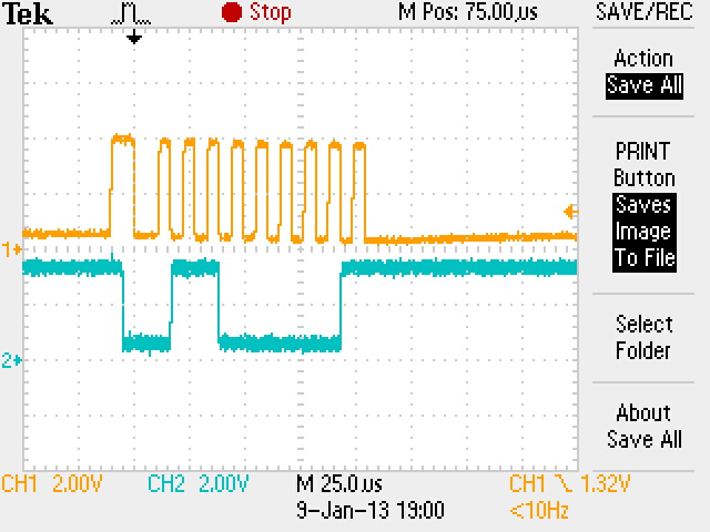
(observed on Digital Storage Oscilloscope) . Only difference observed is with the edge on which the I2C data changes with respect to I2C clock. We are not sure if
that is the issue.
For your reference the waveforms are attached.
TEK0000-Issue.jpg -> Waveform captured with Serializer and Deserializer connected in-between.
TEK0001-Working.kpg -> Waveform captured with Camera sensor directly connected to DM6347 EVM.

What could be the reason due to which the camera sensor I2C communication is not working in case of Serializer and Deserializer introduced in-between.
Is there anything we are not configuring properly or what else we should be monitoring / ensuring to help us in identify and resolve the problem?
A quick reply in this regard is highly appreciable.

