This thread has been locked.

If you have a related question, please click the "Ask a related question" button in the top right corner. The newly created question will be automatically linked to this question.

TUSB8040 functional problem

Other Parts Discussed in Thread: TUSB8040, TPS74801, TUSB8040A, PCM2903C

Hello!

I am actually trying to build an USB3.0 hub with the TUSB8040 Chip.

The problem is that is not working. I tried to build it very similar to the schematic of the evaluation board.

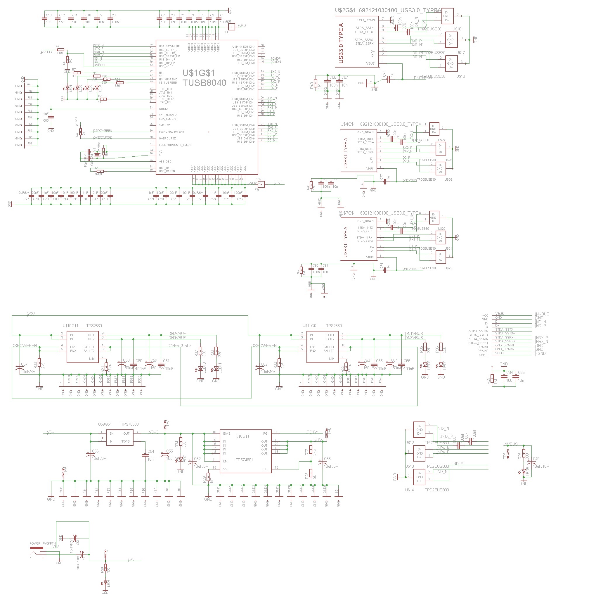
If the board is turned on, the TUSB8040 activates the 4 downstream ports (LED8, LED9, LED10 & LED11 are switched on) and nothing more happens.

I thought it might be a problem with the reset, because the chip was not reacting on a manual rest signal and I also have read in the Errata

about problems with it and the sequencing of the power rails. So I added the additional rest circuit with the TPS3808G33 from the evaluation board and to provide the TPS74801 direct from the 5V rail.


The chip is still not running. He is still not reacting on a manual rest signal or USB device and only the 4 downstream ports are activated. The LED's for

HS, SS, HS_Suspend and SS_Suspend are switched off. I have already checked the power rails and the oscillator and they look good (low noise and values are correct).


Can you please give me any advice what the problem could be.

  • Hi Thomas,

    The schematic looks clean.  When do the downstream LEDs turn on?  When the upstream port is connected?  What is the upstream port connecting to?  Is it an embedded system?

    Thanks,

    Julie N

  • Hi Julie,

    If the power is pluged in, the downstream LED's immediatly turn on. There is no difference if the upstream port is connected or disconnectet.

    The board is connected to a normal PC with Windows 7. I also tried to connect it to a USB2.0 and a USB3.0 port but it also makes no difference.

    The PC shows no message if the board is pluged in.

    I also have the evaluation board of the TUSB8040A and this works fine with this PC.

    best regards

    Thomas

  • Can you tell what the state of the PWRONz_BATEN terminal is?  Is there a good connection between the thermal pad and ground?

    Thanks,

    Julie

  • Hi,

    I made today a chart of all pins and measured the dc voltage direct on the chip. During the measurement, I noticed at pin 45 (USB_DP_DN3) a voltage of 3,6V, which is higher than the supply voltage. Also I noticed the difference to the coresponding pins of the other downstreamports. USB_DP_DN3 and USB_DM_DN3 are routed on the board to a circuit with a PCM2903C. In this circuit was a fault, which caused the 3,6V on the pin. I removed the circuit fromt the lines and measured a voltage of 0,01V, but the chip is still not working.

    Is it possible that the 3,6V damaged the TUSB8040?

    The thermal pad is connected with 9 vias to a separate groundplane, like it is recommendet in the datasheet.

    pin name dc voltage [V]
    1 VDD11 1,1176
    2 USB_DP_DN0 0,01
    3 USB_DM_DN0 0,01
    4 VDD33 3,297
    5 VDD11 1,176
    6 USB_SSRXP_DNO 0,215
    7 USB_SSRXM_DNO 0,215
    8 USB_SSTXP_DNO 1,17
    9 USB_SSTXM_DNO 1,17
    10 VDD11 1,176
    11 VDD11 1,176
    12 USB_SSRXP_DN2 0,24
    13 USB_SSRXM_DN2 0,24
    14 USB_SSTXP_DN2 1,17
    15 USB_SSTXM_DN2 1,17
    16 VDD11 1,176
    17 USB_DP_DN2 0,01
    18 USB_DM_DN2 0,01
    19 VDD33 3,29
    20 VDD11 1,176
    21 VDD33 3,297
    22 HS 0,01
    23 SS 0,01
    24 HS_SUSPEND 0,01
    25 SS_SUSPEND 0,01
    26 VDD11 1,175
    27 JTAG_TCK 0
    28 JTAG_TMS 3,2
    29 JTAG_TDO 0
    30 JTAG_RSTz 0
    31 JTAG_TDI 3,2
    32 VDD11 1,175
    33 GRSTz 3,29
    34 SCL_SMBCLK 0,003
    35 SDA_SMBDAT 0,03
    36 SMBUSz 3,2
    37 VDD11 1,175
    38 VDD33 3,295
    39 PWRON0z_BATEN0 0
    40 OVERCUR0z 3,26
    41 FULLPWRMGMTz_SMBA1 3,21
    42 VDD11 1,17
    43 VDD33 3,295
    44 USB_DM_DN3 0,01
    45 USB_DP_DN3 3,63 0,01
    46 VDD11 1,17
    47 USB_SSRXP_DN3 0,228
    48 USB_SSRXM_DN3 0,224
    49 USB_SSTXP_DN3 1,17
    50 USB_SSTXM_DN3 1,17
    51 VDD11 1,173
    52 VDD11 1,173
    53 USB_SSRXP_DN1 0,259
    54 USB_SSRXM_DN1 0,259
    55 USB_SSTXP_DN1 1,171
    56 USB_SSTXM_DN1 1,171
    57 VDD11 1,175
    58 VDD33 3,297
    59 USB_DM_DN1 0
    60 USB_DP_DN1 0
    61 VDD11 1,175
    62 USB_SSTXM_UP 1,17
    63 USB_SSTXP_UP 1,17
    64 GND 0
    65 USB_SSRXM_UP 0,025
    66 USB_SSRXP_UP 0,025
    67 VDD11 1,175
    68 VDD33 3,297
    69 USB_DM_UP 0,01
    70 USB_DP_UP 0,01
    71 VDD11 1,175
    72 VDD33 3,297
    73 USB_VBUS 0,497
    74 XO 0,78
    75 VSS_OSC 0,02
    76 XI 0,783
    77 VDD33 3,297
    78 USB_R1 0,508
    79 USB_R1RTN 0
    80 VDD33 3,297

    Regards

    Thomas

  • Hi Thomas,

    3.6V should not be enough to damage the TUSB8040, but if there was a fault condition and the voltage ranged higher the device could have been damaged.

    The only use case where the downstream port power would on but there would be no upstream connection, is if battery charging is enabled, which it isn't in your design.  I can't see any reason for the device to behave this way unless it is damaged.

    Regards,

    Julie

  • Hi Julie!

    I orderd a new TUSB8040 and replaced it, but it is still not working. There is no difference between the old and the new one.

    Are there any necessary tricks at the routing of the board? I have tried to route it like it is recommendet in the design guide(http://www.ti.com/lit/ml/slla312c/slla312c.pdf).

    I have used a board with a 4layer FR4 stack. Which material is used at the evaluation board and could make this a difference?

    Is there a bigger chance to get the TUSB8040A running? Then I would try to redesign the board and use it instead.

    Regards,

    Thomas