This thread has been locked.

If you have a related question, please click the "Ask a related question" button in the top right corner. The newly created question will be automatically linked to this question.

dV/dt issues with ISO7641FMDW digital isolator

Other Parts Discussed in Thread: ISO7641FM, ISO7641FC, ISO7241C, ISO7241M

We have recently upgraded a design using the ISO7241CFDW by the newer ISO7641FMDW. However, we are running into issues when operating under high dV/dt.
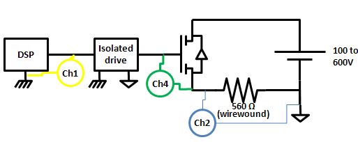
The application is an isolated high side load driver that operates at up to 600V at 10kHz.

The issue consist of a wrong level transmitted by the isolator and appears only with the ISO7641 operating at voltages higher than 360V and hard switching condition (high dV/dt) as seen on screenshots below

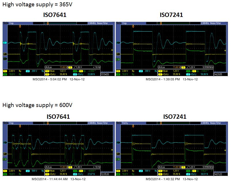
When probing directly on the isolator output, it can be seen that the ISO7641FMDWincorrectly transmits the PWM information. Isolator supplies (3.3V on primary and 5V on secondary) remains constant during the test so it can be assumed that this is not a "fail-safe" output (which happens to be low on ISO7641 and high in ISO7241)

The same test are run with both isolators (and some competitors isolators) and only the ISO7641FMDW shows this problem.


Has Texas Instruments identified this issue before? Are there any known workaround for this issue?

  • Hi Raul,

    Can you send a zoomed in screen capture of the first rising edge? We want to see what's happening during that pulse on channel 4. 

    Also, how are you measuring these signals? I believe most oscilloscopes tie the grounds of the different channels together internally, so that may be something to consider. 

    Thanks,
    Jason Blackman 

  • Dear Jason,

    Primary side waveform (Channel 1) is measured using a regular scope probe (non isolated, 1:10, BW 300 MHz) while secondary side waveforms (Channel 2 and 3) are measured using differential probes (isolated, 1:500, BW 100 MHz) to avoid grounding issues

    Unfortunately, I don't have any zoomed screenshots.
    Best regards

    Raul

  • I think the ISO76xx data sheets gave some warning on high DC-common-mode issues with these ultra-low current isolators. Basically the ISO72xx is the most stable available. In gate drive applications you want to have some higher driver currents to withstand any di/dt  noise transients.

    Could you please explain why you wanted to switch from the successful ISO72xx trials to the ISO76xx series?.

    Thank you, Thomas

  • Dear Thomas,

    From datasheets I understand that both components should withstand very high common mode transients (CMTI 25kV/µs min, 50kV/µs typical) which are 5-10 times higher than the application transients and I have not found any warning on high DC-common-mode issues

    The main reasons for the upgrade to the ISO7641FMDW were

    1. Higher working voltage allowed (1414Vpk vs only 560Vpk) which should increase reliability at high voltages
    2. Lower current consumption. This is specially important on the secondary side on low/medium power applications
    3. Failsafe low which greatly simplifies secondary side electronics

    Given the above advantages, there are still some applications were the ISO76xx may prove superior to the ISO72xx but we must first understand what are the safe dV/dt (or di/dt) limits of the components

    Thanks again for your time

    Raul

  • Hello Raul, I was referring to Note 1) at the bottom of page 16 of the ISO7641FM data sheet which suggests: 1) For applications that require DC working voltages between GND1 and GND2, please contact Texas Instruments for further details.

    Anyway, your response makes perfectly sense. The behaviour of the ISO7641 however does not.

    My question now is: Would it be possible for you to measure the voltage difference between GND1 and GND2 at the isolator?

    I'd like to get as much information as possible for my test engineering team and see what they can verify.

    Thank you and best regards, Thomas

  • Hello Raul,

    our test engineers have the following suggestion:

    Since the issue is occurring during high dV/dt it may be the ISO7641FM is responding to transient energy coupling onto inputs given the ISO7641FM does not have input filters. 

    Hence, could you consider using the ISO7641FC in your application which includes integrated noise filters?

    Thank you, Thomas

  • Hello Thomas,

    Voltage shown  channel 2 of scope screenshot above is already very similar to the voltage difference between GND1 and GND2 of the isolator. It is basically a hard switch of high-side driver. Unfortunately I don't have any more a prototype with ISO7641FM mounted to take more detailed screenshots

    Thanks for your suggestion about the ISO7641FC, I think it is worth a try given the many advantages of the ISO76xx series but in the short-term, I may consider sticking with the the ISO7241C for a while. Does the 150Mbs version of the ISO72xx series (ISO7241M) lacks the integrated noise filter? Do you think it may also present similar problems when used with high DC working voltages?

    Thanks again for your support

    Raul

  • Hello Raul,

    you are correct, the ISO7241M has no noise filters and most likely will give you similar problems. The fix of high DC common-mode between GND1 and GND2 is currently under re-design. Frankly when i looked on your original scope shots I thougth at first that the ISO7641 lacks of drive capability. However, I have seen similar issue with opto-coupler design where large di/dt coupling into the inputs occurred.

    Unfortunately you are already advanced in your PCB design. Otherwise I would have suggested our isolated IGBT driver ISO5500. But for now please go ahead with the ISO7641FC if you can.

    regards, Thomas