This thread has been locked.

If you have a related question, please click the "Ask a related question" button in the top right corner. The newly created question will be automatically linked to this question.

TUSB2046B Issue with DownStream Ports

Other Parts Discussed in Thread: TPS2044, TUSB2046B, SN75240

Hello guys, I am designing a  self powered board based around the TUSB2046B, and am using a TPS2044 power switch, and a few SN75240's for ESD protection on all of the ports. I just got the bare boards in yesterday and got everything populated. I did have to make one change that I somehow missed, I had to add four 10k pull up resistors to each of the OverCurrent pins on the TPS2044. Once everything was in place, I plugged it up to my PC and applied 5V to the board, the computer saw the hub okay and loaded the drivers fine. I can check my device manager and I can see the USB Hub and everything seems to be working properly with the board. However when I put something in one of the four downstream USB ports, it does not do anything, and sometimes gives me  a USB Device Not Recognized warning. I am getting about 5.25 V on each of the four V+ lines on all of the downstream ports. I have been doing some research and found that the RESET pin (pin 4) has to have some sort of a pulse or an RC circuit attached to get everything to work, however it seems like I wouldn't have gotten the drivers to load and the hub recognized if that was the case. I know the RC filter suggested is a 15K resistor and 1uF cap, could someone please show me a schematic or picture of exactly how this needs to be implemented into the circuit? I would greatly appreciate it. If someone could give me a hand and some tips and suggestions as to what I might be able to do to fix this problem. Any and all help is greatly appreciated. Please let me know what additional information you guys need to help and I will be glad to provide that for you. Thanks again very much for all of your time and help.

  • Hello,

    It does seem like your problem is the floating Reset, you can drive this signal with an RC circuit like the below picture, also please attache the complete schematic for a better review.

    Regards.

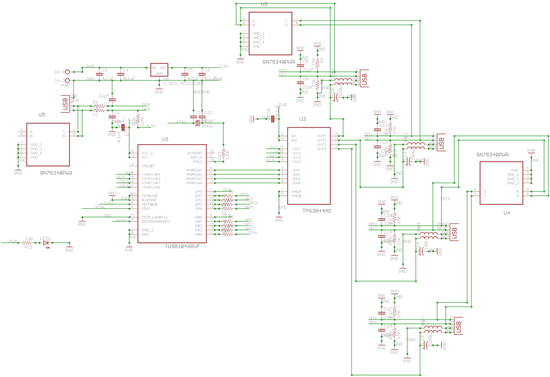
  • Hello! Thanks very much for the reply. I just wanted to verify... in the schematic that you posted, the resistor is supposed to be 15K and the capacitor is supposed to be a 1uF? I just ran a fly wire to the middle of a 15k resistor and a 1uf polarized capacitor, connected the negative on the cap to GND and the other side of the 15k resistor to my 3.3v reg. I am still not having any luck with that. I have added on the four 10k resistors coming off of the overcurrent pins and tied them to 3.3v as well. I am stuck, in Device Manager everything looks good, but whenever I plug in a USB device it does not see anything, the voltage is staying consistent on the V+ on the downstream ports as well. I am attaching a picture of the full schematic, hopefully you will be able to see everything. This schematic does not include the 10k pull ups or the reset circuit, I have added them however. If you have any more ideas it would be greatly appreciated. Thanks very much for your time and consideration, I truly appreciate it.

  • Hello,

    Is the crystal oscillating? 

    Is the SUSPEND output active?

    Can you verify the power-up Reset timing?  (1ms to 3ms low after Vcc has reached its 90%)

    Regards.

  • Hello, Thanks for the reply.

    I will check the crystal whenever I get home, but I am pretty sure I checked it and it was pretty much right on 6MHz.

    What should the output of the SUSPEND pin be?

    And what would be the best way to verify the power up reset timing? Just use my scope and hit the power? Just not 100% sure how to be sure my VCC is at 90%?

    Thanks very much, I will get back with you once I get home and check everything out. Thanks again.