This thread has been locked.

If you have a related question, please click the "Ask a related question" button in the top right corner. The newly created question will be automatically linked to this question.

TUSB1310A

Other Parts Discussed in Thread: TUSB1310A

Hi,

I'm using TUSB1310A with Synopsys xHCI usb host controller on our FPGA (Altera) prototype.

USB2.0 (over ULPI) works without any issue. However I'm getting weird behavior on USB3 IF.

On the first time firmware runs, the phy returns no receiver is detected while on the 2nd time the receiver is detected.

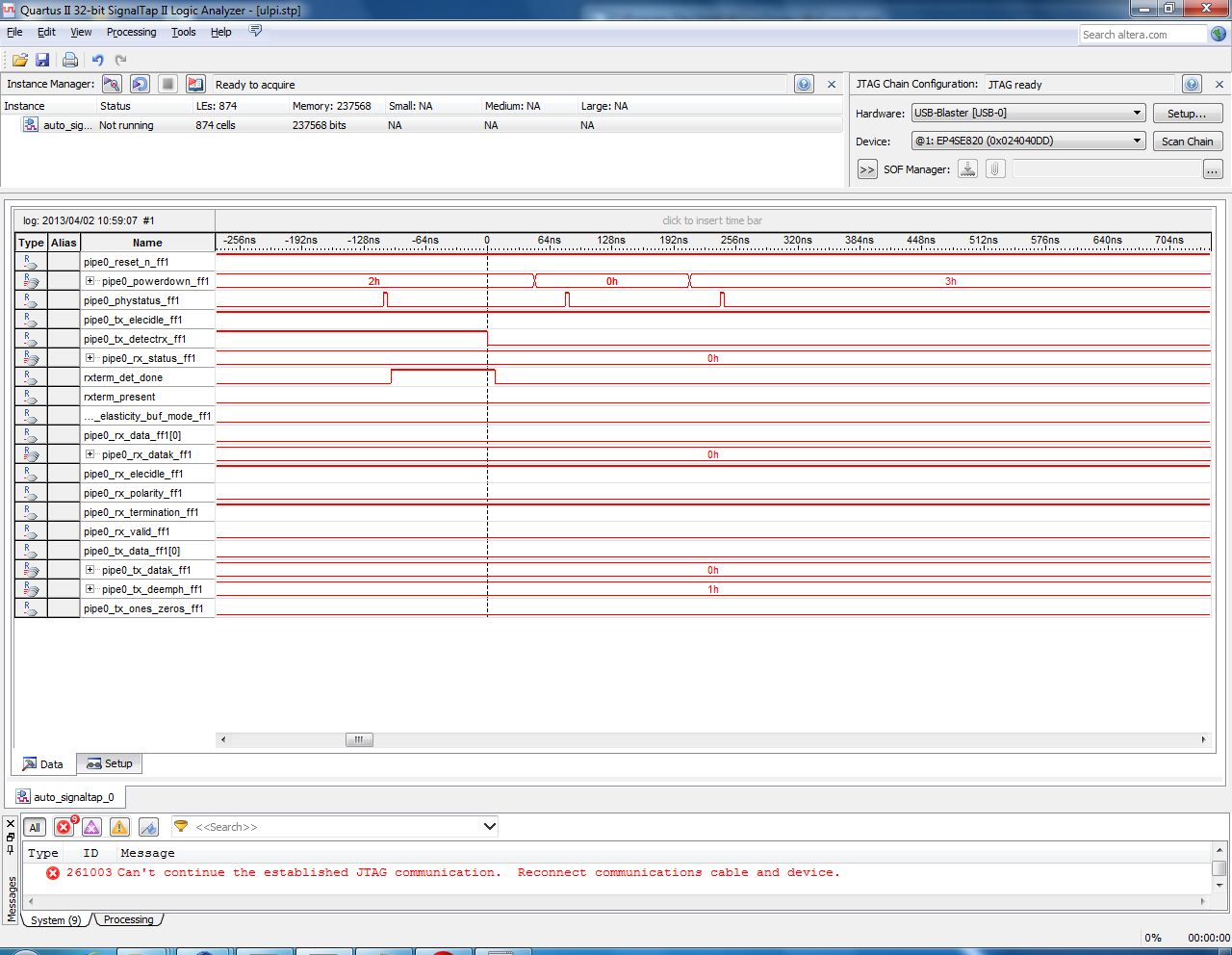
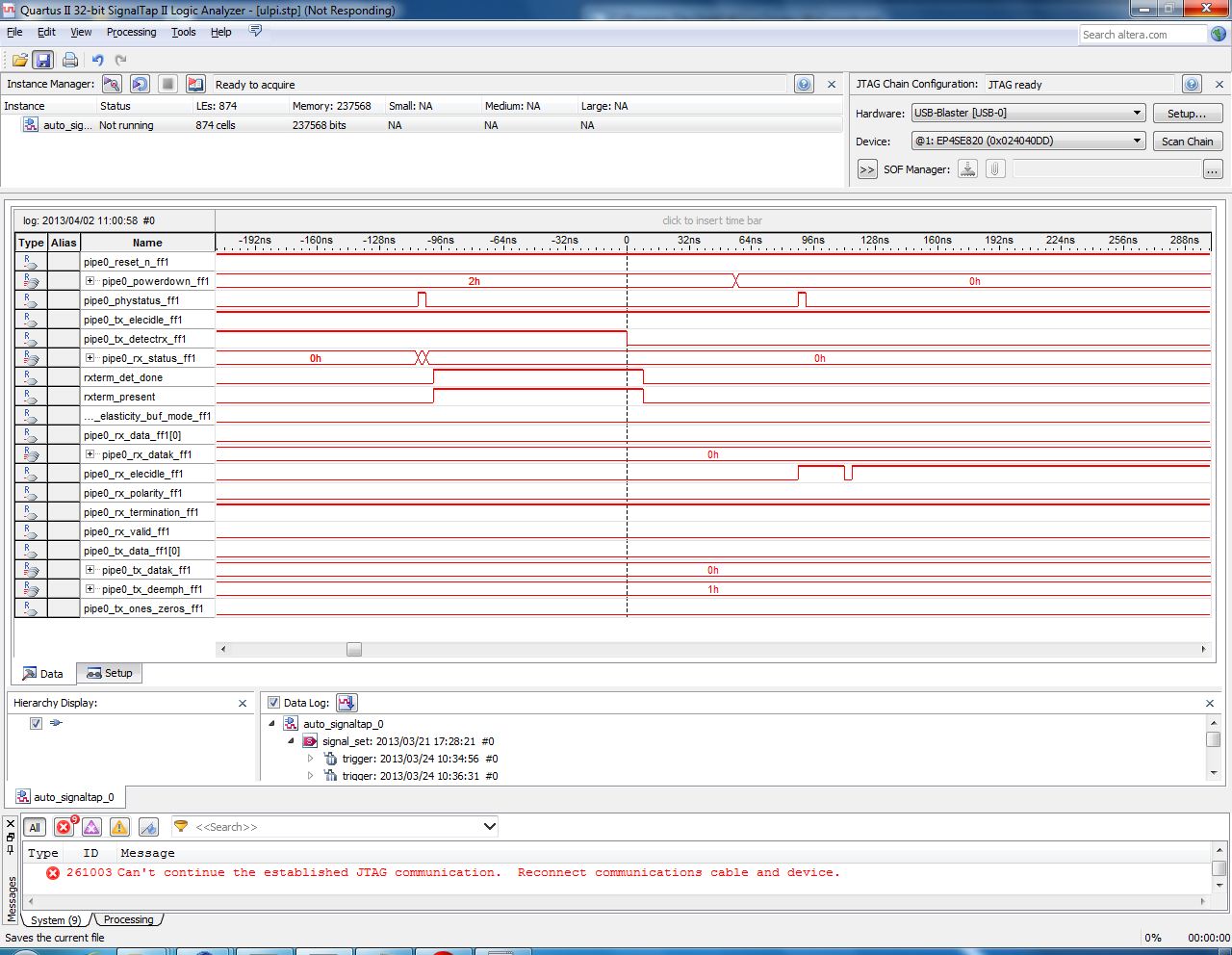
On the waveform, there is an observable difference on rx_elecidle line behavior but I have no idea what is causing this.

Reset de-assertion in failing case:

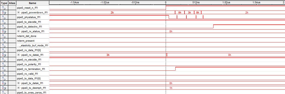
and then on  tx_detrx falling edge:

On success it looks like this:

I use 40MHz XTAL, strapping values are being set by pull registers, RESETN is de-asserted after FPGA isprogrammed which takes more than 1sec, so PS and strapping values should have been stable. 

I would appreciate any help...

Thanks

  • Hello,

    We are reviewing your question and we'll reply soon, is your FPGA 250MHz capable?

    Regards.

  • Yes it is.

    My fist suspicion was timing failure on the PIPE interface but further debug showed that timink does look good.

    Then I found out the failure is happening on RX detection.

    Thanks.

  • Hello,

    What is the difference between "...the first time the firmware runs..." and "...the second time..."

    How are you connecting terminal VBUS?

    Do you have a SS downstream device connected  to the TUSB1310A?

    Can you place an external pull down on terminal RX_ELECIDLE and see if your application works fine.

    Are you following the power-up sequence described on Datasheet Section 3.1?

    Regards.

  • Hi,

    A) The first time is the first time after I turn on the FPGA board- it doesn't depend on the time we are waiting before running it though.

         The second time is resetting and re-running the FW (without power off or re-loading the FPGA).

    B)  VBUS connection (PW_VBUS) is an external 5V source):

    C)  A SS device is always connected.

    D)  RX_ELECIDLE is tied to GND with a PD resistor because it's a strapping pin and we are using a crystal clock input.

    E)  I think I do.. I describe what I do at the end of my original post. Is something missing there?

    F)  An additional question. If we want to run electrical tests on our setup- how can we do it? (eg, make the phy to transmit a test pattern)

    Thanks,

    Yoni

  • Hello,

    In order to discard a power-up timing issue please try the following:

    VBUS should be connected via voltage divider as specified in datasheet, this terminal is not 5V tolerant.

    Reduce the power-up reset timing to the PHY, you are waiting 1sec after power is applied to the PHY, can you reduce this time to below 100ms? If not, can you make a assertion/deassertion of the GRST after your FPGA is fully configured? 

    Regards.

  • Hello,

    Sorry for not updating for a while.

    In the meanwhile- I wasn’t able to root cause the root cause, but disabling SS suspend in xHCI made the xHCI to overcome and eventually detect the device.

    So even though I don’t have the time to do the requested testing, this is not an issue for us anymore.

    Thanks,

    Yoni