This thread has been locked.

If you have a related question, please click the "Ask a related question" button in the top right corner. The newly created question will be automatically linked to this question.

SERDESUB-21USB I2C communication in Display mode


Hi,

I am currently evaluating the SERDESUB-21USB kit and I am experiencing problems with the I2C interface when operating the SERDES chip set in the Display mode, and I was hoping somebody could point me in the right direction as to what might be causing me the problem.

The SERDESUB-21USB link is working reliably (Lock signal stable, witnessed by setting a trigger for falling edge) and I am providing a 20 MHz signal on the Ser (PCLK pin), for which I am recovering reliably at the Des end (PCLK pin). Also the GPIO pin(s) functionality is working correctly; therefore I am confident that the SERDES link is working reliably.       

A Diagram of my I2C set-up is shown as follows:-


With reference to the SERDESUB-21USB (P21) User’s Guide the Dill switches for configuring Master / Slave relationship (M_S pin) have been set as follows:-

  • DS90UB903Q = H (Slave)
  • DS90UB904Q = L (Master)

I2C bus speed at the Master is configured as 100 kHz

Also in line with configuring the set-up the following register values have been set:-

SER 0x06 = 0xC0 (Default anyway at power-up)

SER 0x07 = 0x9A

DES 0x08 - 0x17 = 0x00 (Default)

The problem I am experiencing is when trying to send a command to the AR1021 (Touch screen controller), which have been verified as working correctly when not passing the I2C over the SerDes link.

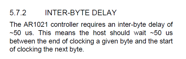
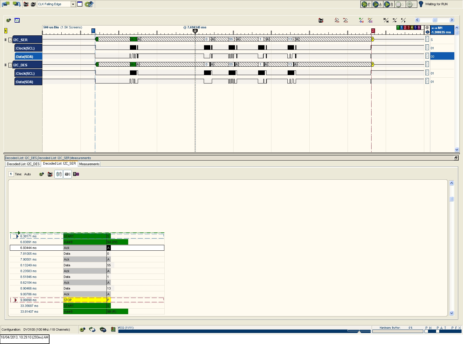
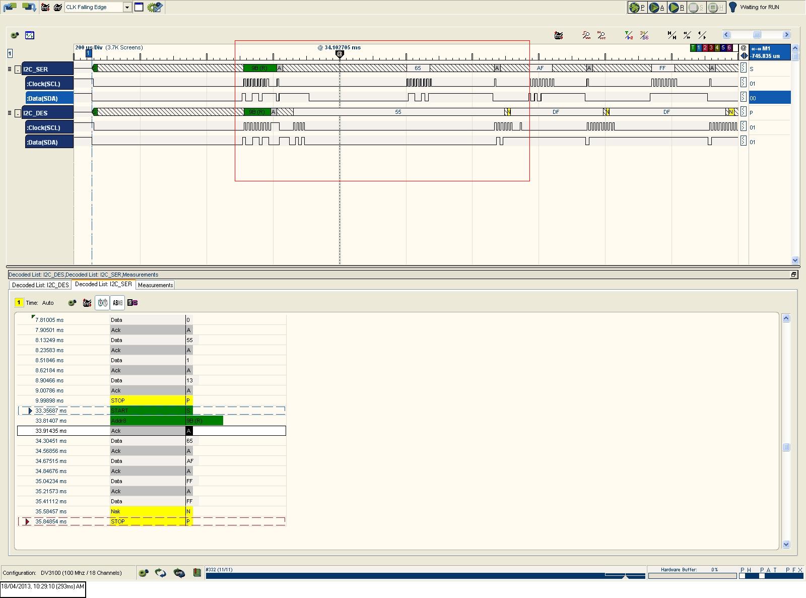
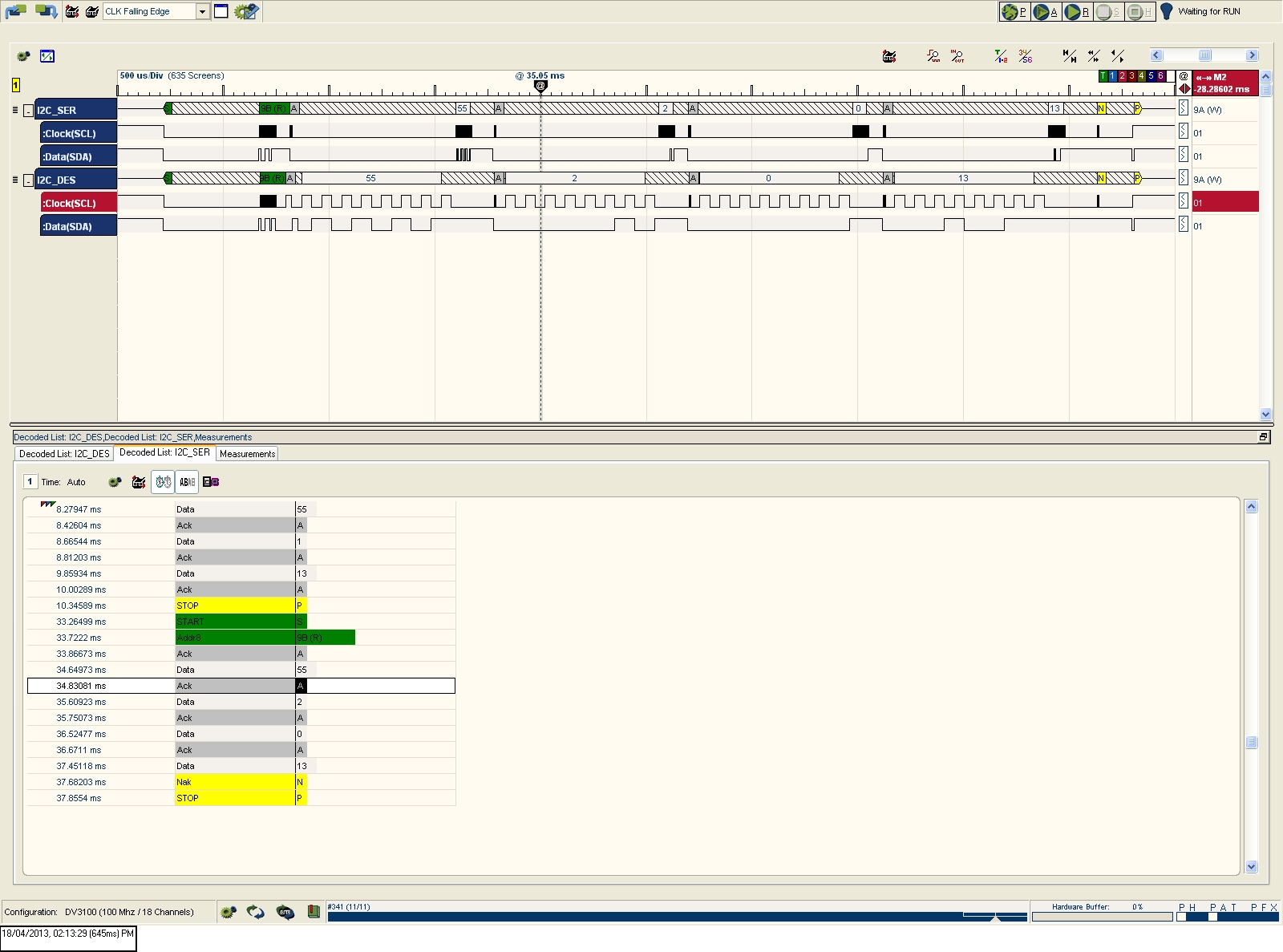
An example command (Bytes seen) has been provided within the attached file (Image insertion proivded poor quality) see screen shot of the logic analyser image highlighting the issue I am seeing. Logic Analyser connections are made at I2C_SER at the O/P of the Microchip Serial Analyser and I2C_DES at the O/P of the DS90UB904Q Deserialiser.

Disable Touch

Send: - 0x9A, 0x00, 0x55, 0x01, 0x13              This is sent O.K and timing seems O.K (Approx 1us delay between SER and DES clock pulses)

Receive: - 0x9B, 0x55, 0x02, 0x00, 0x13         Clock pulses are seen on the Des line, when 0x55 is sent by the AR1021 however these are not being re-produced on the Ser I2C bus and timing appears to become sparadic ?

From looking at the datasheet and also from correspondance from Microchip both the Master (Serial Analyser) and Slave (AR1021) both support clock stretching....

Any ideas on resolving this issue would be appreciated as I am keen to implement this chip set in my future design.

Thanks Lee Smith


  • Hi All,

    I am adding this update as I have managed to move on a little further with this problem.

    I have found that it is possible to get the AR1021 to function correctly by pre-scaling the SCL clock line to 11 kHz (Lowest setting available). I managed to do this by setting register 0x06 to 0x5F on the DS90UB904Q. Please see attached image detailing a successful receive captured by the logic analyser which I have tried to add (Appologies if this has over written the previous one; however it is more relevant).

    The conclusions I have drawn from this is:-

    1) During a 'send' message both the Ser and Des appear to be almost in sync and only a very small propagation delay exists (In the order of approx 1us) and no errors are seen with both devices set to 100kHz.

    2) During a 'receive' message the Ser and Des appear to be out of sync. If you reference to the attached image what appears to be happening the Des generates the SCL pulse on it's local bus without the Master Ser having control of the SCL line. It appears as though the Ser is held by clock strecthing until the entire byte has been read into the Des, where upon the 8th clock pulse the SCL is released to the Ser so it can reproduce the data back to the master.

    Can somebody please look into this and clarify if this is expected behaviour ? Or if there is anything else I can do with this chip-set to fix this problem other than what I have already done ?

    For my particular application I am not confident this is a solution and I do not want to slow the bus down, however once the I2C is under S/W control other than using a GUI like I am at present we may practically be able to implement delays into the standard I2C recieve command.

    Please can somebody advise / clarify on the previous messages

    Lee Smith  


  • Hi Lee,

    Based on the ‘Disable Touch_Recieve.jpg’ plot, this is not the expected behavior of the DES. During the time read byte is send out on DES side to AR1021, the SER will hold SER_SCL low and DES will generate 8 clocks pulses on DES_SCL to receive data from slave device. Following the DES_SCL 8th clock, the data is then transmitted back to SER to regenerate the corresponding read data to host controller. The ‘Disable Touch_Recieve_11kHz.jpg’  plot is correctly showing the proper timing and i2c transactions. What is odd is the on the plots is the DES_SCL clock is gapped after 4th clock pulse and didn’t complete the read command but read data is transferred back to SER before completion. The DES_SCL clock pulses should be continuous (w/o gaps) during this read phase. Can you confirm the AR1021 is not holding/driving the SCL line during this period? So only 11kHz setting works and all other frequencies settings fail?

    Dac Tran

    SVA APPS

  • Hi Dac,

    Thanks very much for the response,

    I have tried all other DES_SCL frequencies and yes only the 11 kHz setting works correctly.

    I have again monitored the DES SCL & SDA lines with the logic analyzer, and what I have found is that the problem (missing a number of clock cycles) gets worse as I increase the SCL frequency on the DES (Via the prescale register 0x60); the results I found were as follows:-

    11 kHz = O.K All, 8 SCL clock cycles clocked out by the DES (Without a gap) and the correct data is transferred back to the SER

    33 kHz = Failed, A time gap is added after the 7th clock cycle, where the SER then transmits the 8 bits of data incorrectly, hence missing the 8th clock cycles after the gap 

    50 kHz = Failed, A time gap is added after the 4th clock cycle (As seen), where the SER then transmits the 8 bits of data incorrectly, hence missing the 7th-8th clock cycles after the gap  

    100 kHz = Failed, A time gap is added after the 6th clock cycle, where the SER then transmits the 8 bits of data incorrectly, hence missing the 5th-8th clock cycles after the gap  

    125 kHz = Failed, A time gap is added after the 3rd clock cycle, where the SER then transmits the 8 bits of data incorrectly, hence missing the 4th-8th clock cycles after the gap  

    I have tried another I2C device and this does function correctly at 100 kbps, and all the I2C timings and transactions are as per your description and matches what I see at 11kbps (Obviously the SCL freq is different), which does point to a compatability problem between the SerDes chip set and the AR1021 touch screen controller.

    I am unsure if it is the AR1021 that is holding the SCL line low or the Des, and what I have done is to By-pass the SerDes chip set and run the same command (From a GUI supplied for the touch screen as part of the Eval kit) as I have shown in the previous images and what I have found is that there is a delay of approx 500 us after sending the Read address (0x9B) before starting to clock out the data from the AR1021 and I'm wondering if a delay is needed at the DES end if that is possible (See Attached image) ?.

    Also I have noticed that the AR1021 after sending it's ACK to the Read address 0x9B (Low on SDA on 9th SCL) it drives the SDA line high before taking it low again ready for presenting the first data bit on SDA. The time from SDA going high (After ACK) to going low for first bit of Data (0x55) is measured as 30 us.With reference to the AR1021 datashhet section 5.7.2 P24 (See attached image)

    Do you have any ideas of how I can solve this problem so I run at 100 kHz ?. I cannot see any way to delay this in the DS90UB904Q datasheet.

    Please advise and thanks in advance

    Lee


  • Hi Lee,

    Based on the information you provided, the AR1021 is controlling the I2C bus in some manner during the read phase. This is shown on the ‘0842.30us_5F00_delay.png’ where the I2C SCL/SDA lines are driven low after the 0x9B read byte; otherwise the I2C lines would be released (idle high). The AR1021 datasheet section 4.4 Master read bit timing step 4 mentions:  Master monitors SCL, as the AR1021 may be“clock stretching”, holding SCL low to indicate that the master should wait. Unfortunately, the I2C controller on the DES does not have this type of ‘intelligence’ to sense the bus activity. Therefore, there will be some sort of bus contention/conflict which will result in interoperability issues. There is also no option on 904 to force a delay in the read operation other than the SCL prescaling.

    Dac Tran

    SVA APPS

  • Hi Dac,

    Firstly thanks for your response.

    With reference to my previous post I have looked at the AR1021 data-sheet again and section 5.7.2 "Inter-Byte Delay" is specific to the SPI timing therefore please dis-regard this.

    With reference to your previous post; I agree and it does appear to be the AR1021 pulling the clock line low (After 30us) which in my understanding is a function of clock stretching if the AR1021 device isn't ready to respond, however it does initially start to respond with the first 4 clock cycles before either the DES or AR1021 pull the SCL line low . The I2C_DES SCL is initially released approximately 44 us after the SCL is initially pulled low to allow the 8 clock cycles to begin. I have opened a support request with Microchip on this problem to clarify the exact operation, and hopefully explain what is happening with the AR1021 so we can nail down the problem.

    I am surprised however with your last comment detailing the I2C controller on the DES does not have the 'intelligence' to monitor for clock stretching of the slave. Can you please clarify this to be the case ? With reference to the DS90UB903Q data sheet P24 section "Slave Clock Stretching" this is not how I understand this.

    I will update once I receive a response from Microchip

    Lee

  • Hi Lee,

    When I describe the I2C controller on the DES does not have the 'intelligence' to monitor for clock stretching of the slave that refers to the chipset not supporting bus arbitration. Background info on slave clock stretching, this method is used by slave to delay the host controller (by holding SCL Low) in order for the process the commands across link and synchronize with remote devices. So the serdes can function as an I2C slave proxy or master proxy depending on the I2C mode. When serdes behaves as a master (DES in this case), device does not support clock stretching from a slave device. The chipset’s internal master I2C controller expects to solely control the bus with the attached slave device. The 903/4 is 1st gen FPD-Link III chipsets with bidirectional interfaces using I2C which has limited bus management capabilities (ie multi-master, arbitration, etc). However these features are offered in our other chipsets such as DS90UH925/926.

    Dac Tran

    SVA APPS

  • Hi Dac,

    Thanks for the response, I've been working on another project so I've been unable to pick this up again over the past few week. This further confirms my suspicions that the clock stretching is not fully supported in the 903/4 when the Des behaves as the Master (During a Read), which explains why only slowing down the SCL speed to 11kHz allows this application to function correctly, although I am not confident this is robust.

    I have received a response from Microchip confirming that the problem I am seeing is typical of timing violations where clock streching would nominally be performed by the AR1021 and the Master would respond to this (904 Des in my case) by not driving the SCL line. The figure they gave me for a inter-byte delay was 50 us which is referenced speciifcally for SPI in there datasheet (I had sent this in a previous response to you when I spotted this myself); however they assure me this would also be relevant for I2C communication.

    I could implement a 50 us delay (Or greater) between bytes in the read command from the Master; however with my understanding now of how the 903/4 device operates this would not be passed through to the Des, as the 8 clock pulses are immediately sent after the address, therefore I do not think the 903/4 Ser/Des would be suitable for my application without changing the touch screen controller.

    I have looked at the other FPD-LinkIII Ser/Des (18/24-Bit) for which there are only two other devices:- DS90UB925Qand DS90UH925Q please can you advise me if either /or both of these devices would solve my problem i.e. support clock stretching when the Des behaves as the Master during a read command ?

    Can you also advise if it is possible to communicate with more than one I2C device from the Des in the set-up I have, without setting a new Slave ID regisister 0x07 on Des ? I noticed there are several device ID regsiters on the Des 0x08 - 0x0F but I understood this was if the Master was connected to the Des end i.e. Camera mode ?

    Thanks

    Lee Smith