This thread has been locked.

If you have a related question, please click the "Ask a related question" button in the top right corner. The newly created question will be automatically linked to this question.

DS92LX1621 I2C compatibility

Other Parts Discussed in Thread: DS92LX1621

I am attempting to get an Aptina MT9M131 CMOS image sensor connected up to an OMAP L138 processor via a SerDes link DS92LX1621/1622.

The SerDes link is solid and not having any synchronization or lock issues.  My problem occurs while trying to configure the image sensor across the SerDes I2C link.  There are 2 timing issues that I have noticed.  First is that the MT9M131 "2-wire serial interface" is not claiming to be I2C compliant.  And it is not: a 600ns hold time on SDA is required following falling edge of SCL.  The official I2C standard only states that SDA must change while SCL is low - there are no setup or hold times required.  The ideal transition places the SDA change in the middle of the low SCL period.  The second timing issue is with the '1621 master proxy function.  The '1621 is changing SDA simultaneously with the falling edge of SCL, not after the falling edge of SCL, as the I2C standard requires.

Either of these timing violations could cause a compatibility problem, but the two together make for an even worse situation.  As far as I can tell, I have no control to change any of this.  Although the OMAP side of the bus would correctly communicate with the image sensor, the "repeated" side of the I2C cannot.

Any work-around's that I can do?  I'm going to try to delay SDA using a capacitor, but I certainly can't get a 600ns delay.  I suspect much less is actually needed, since I have observed an occasional "ACK" from the part, even with the timing as it is.

I would expect many people to have issues using the I2C functionality of this SerDes pair, since it doesn't really follow the I2C standard.

I have attached several scope traces showing the issues.  There are 2 I2C busses shown: channels 3&4 are at the OMAP, and channels 1&2 are the repeated bus between the Ser and the image sensor.  

Channels 3&4 show the idealized I2C SDA transition point.  

When repeated by the Ser, it can be seen that SDA change is simultaneous with falling edge of SCL.

Thanks in advance for any help or suggestions.

David

  • Hi David,

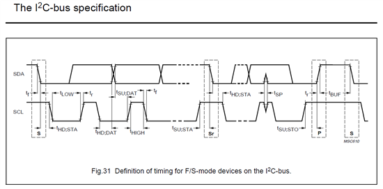
    The I2C timing issue related to insufficient I2C hold time on the image sensor as you mentioned. We had some customers experience similar issues related to I2C timing due to non-I2C compliant devices. These peripherals use their own flavor of I2C protocol; such as 2-wire, serial bus interface, etc. and does not comply with the I2C standard.  The tHD:DAT data hold time I2C bus specification is 0us (min) for this timing. The I2C module implemented on DS92LX1621/1622 complies with the I2C standard. Since the serdes link is a synchronous system, the I2C is based on the falling edge of the SCL clock. Unfortunately there are no registers to adjust the hold timing on Serializer side. However, our newer chipsets such as DS90UB913/914 do have I2C setup/hold time programmability.

    A possible workaround is to delay the SDA line on bus (additional hold time) by adding RC to slow the SCL -> SDA transition. You may experiment with different I2C datarates to achieve this timing. Another method involves regenerating the slave id address programmed on the Deserializer (reg 0x08) to emulate extending the hold time when transmitted across to the Serializer onto the remote i2s bus. For example, set camera sensor SADDR = LOW, the sensor slave address will be 0x90 (1001_000X): this translates 0x90 (1001_000X) -> 0xD8 (1101_100X) by programming DES reg0x08=0xD8.

    Dac Tran

    SVA APPS

  • I would argue that the DS92LX1621/1622 do not strictly meet the I2C timing standard for tHD:DAT.  The timing diagram below shows the definition of tHD:DAT is from valid low on SCL to the begin of change on SDA.  Yes, that time is specified as 0us.  But if SDA changes coincidentally when SCL begins to fall, this is actually a negative hold time, less than 0us.

    With my selected Aptina image sensor, this small difference would still not allow it to work.  A part truly designed to be I2C compliant is required to provide its own internal 300ns hold time on SDA.  If a part does this, then the '1621/1622 would certainly work just fine.  The Aptina image sensor does not claim to be I2C compliant, and it is far from it (requiring 600ns setup and hold times!).

    I did try adding an RC delay to see if that would be enough, but it really didn't help.

    Concerning your "change the address" idea, I'll give you an 'A' for creativity, but it seems way to dangerous and/or flaky for me.

    For now, we just wired up the I2C bus directly (without going through the serializer).  In our final product, we can use a processor local to the image sensor to provide its I2C setup needs (rather than setting it up remotely over the serial link).

    Thanks again for your help and suggestions.

    David