This thread has been locked.

If you have a related question, please click the "Ask a related question" button in the top right corner. The newly created question will be automatically linked to this question.

DP83640 - Incidental CRC and NONOCTET errors with TFTP boot on u-boot 2012.04. ethloop works fine...

Other Parts Discussed in Thread: DP83640

I am trying to TFTP boot a Linux kernel on a Freescale MPC8313e-rdb PowerPC. The bootloader is u-boot 2012.04 where I've added the DP83640 phy driver and the ethloop test case.

The TFTP server is a Ubuntu 10.04 machine with xinetd tftp service.

When I try to load a file (e.g. Linux kernel) through tftp the phy incedentially generate errors (approximately at 1 % of the cases). The tsec driver tells me that I got a CRC and/or a NONOCTET error (0x0004 and 0x0010 resp.) I haven't configured any register, the only thing I've done is reset the PHY by writing 0x8000 in the BMCR.

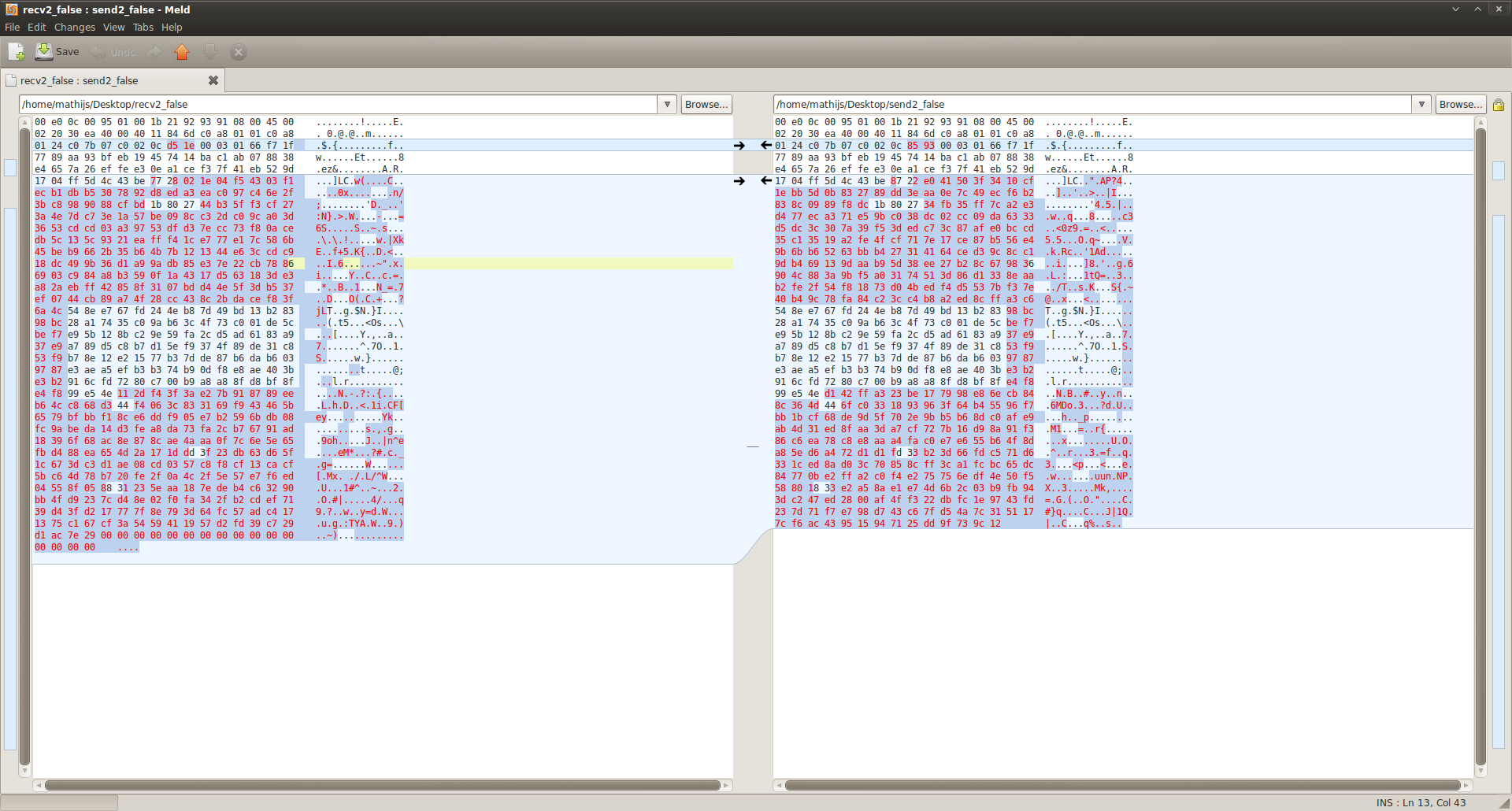
I've tried a 100mbit full duplex, half duplex and a 10 mbit half duplex connection, but all speeds fail in 1 % of the packets. On normal conditions, there are 562 bytes captured by the MAC, but when the faulty packets are received, sometimes 563 or 564 bytes are read.

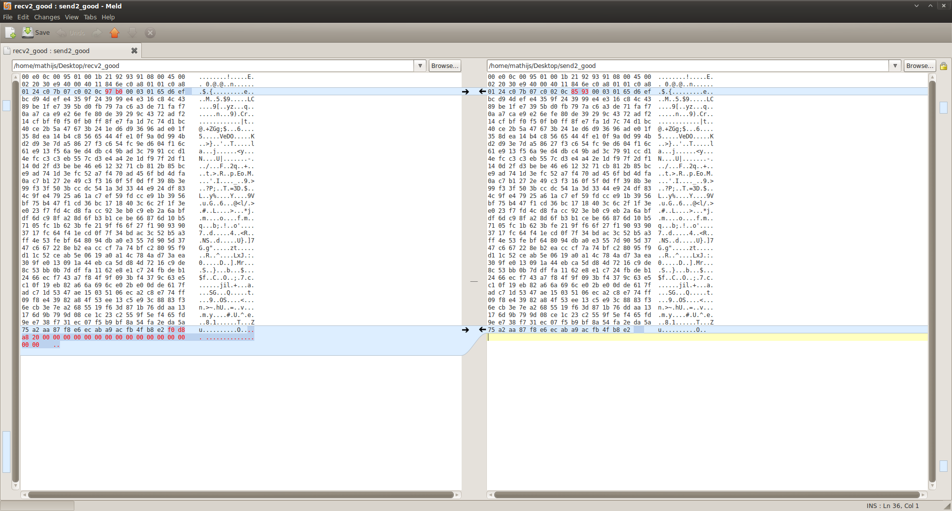
When I memory dump the received packets, and compare them with the send packets something strange shows. Please keep in mind that in the memory dump of the received packets, I print 16 extra bytes, just to show any gibberish when available.

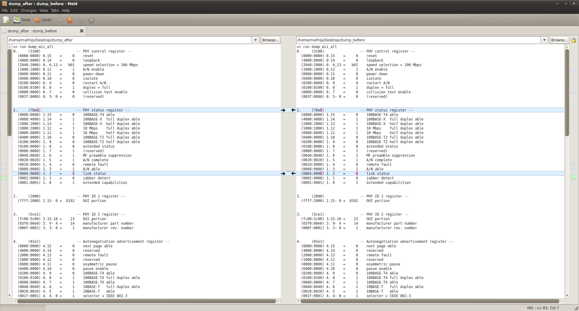
A good packet looks like this (received on the left, send on the right)

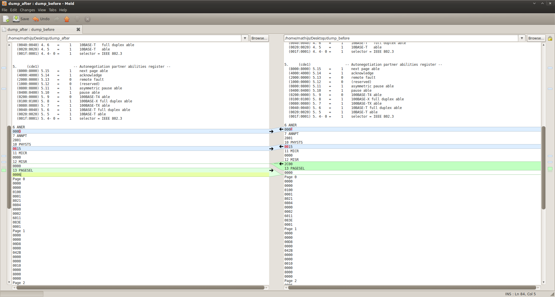
A faulty packet looks like this (received on the left, send on the right)

To determine where the problem may lay, I've enabled the loopback (0x7100 in BMCR) and wrote 1024 bytes to the phy and then read back the data to compare each packet. I've run this test 10.000 times, no errors are generated. Then I've disabled the loopback and inserted an ethernet RJ45 loopback adapter and rerun the tests. No errors are generated. I'm flabbergasted...

What could be the (possible) problem here?

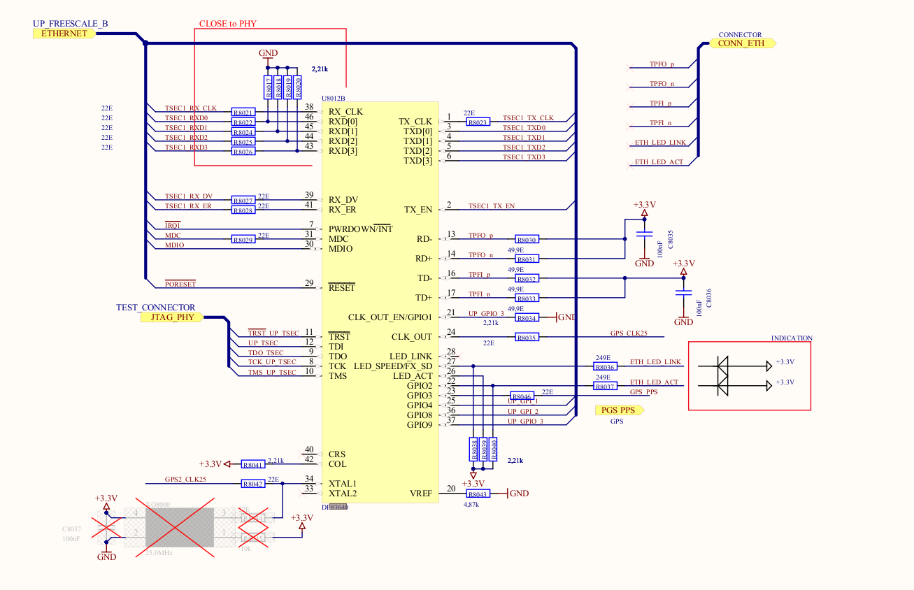
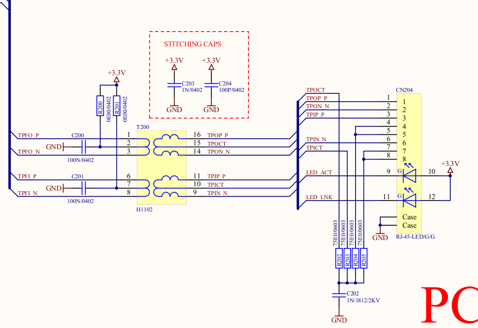
My ethernet chain consists of the following components:

  • Freescale MPC8313E-RDB PowerPC
  • TI DP83640 PHY
  • Pulse Engineering H1102 10/100BASE-T Magnetics

Many thanks in advance and when you need more information, please let me know!

Mathijs

  • Mathijs,

    I have moved your post to the Ethernet forum. To help with better supporting and tracking your future questions in Ethernet, please post any new Ethernet related questions into this forum.

    I can understand why you are flabbergasted.  This is an unusual problem and is definitely not normal or expected behavior. 

    I think it would probably be best to start with a review of the fundamentals of the design.  Could you provide a schematic of your design and a complete dump of the Phy registers?  If you are worried about posting  your schematics to the forum, let me know and we can make alternate arrangements.

    Patrick

  • Hi Patrick,

    First of all, sorry for posting in the wrong section of this forum. Thanks for moving the topic. I'm investigating if I'm allowed to post the schematics, I'll get back to you on that.

    I've dumped the registers as you suggested and reviewed the differences between the default after reset and the state after a successful transfer (e.g. ping test). Those differences are the same compared to a default and unsuccessful transfer (failed TFTP block).

    Here's the complete dump after a (un)successful transfer:

    0.     (3100)                 -- PHY control register --
      (8000:0000) 0.15    =     0    reset
      (4000:0000) 0.14    =     0    loopback
      (2040:2000) 0. 6,13 =   b01    speed selection = 100 Mbps
      (1000:1000) 0.12    =     1    A/N enable
      (0800:0000) 0.11    =     0    power-down
      (0400:0000) 0.10    =     0    isolate
      (0200:0000) 0. 9    =     0    restart A/N
      (0100:0100) 0. 8    =     1    duplex = full
      (0080:0000) 0. 7    =     0    collision test enable
      (003f:0000) 0. 5- 0 =     0    (reserved)


    1.     (78ed)                 -- PHY status register --
      (8000:0000) 1.15    =     0    100BASE-T4 able
      (4000:4000) 1.14    =     1    100BASE-X  full duplex able
      (2000:2000) 1.13    =     1    100BASE-X  half duplex able
      (1000:1000) 1.12    =     1    10 Mbps    full duplex able
      (0800:0800) 1.11    =     1    10 Mbps    half duplex able
      (0400:0000) 1.10    =     0    100BASE-T2 full duplex able
      (0200:0000) 1. 9    =     0    100BASE-T2 half duplex able
      (0100:0000) 1. 8    =     0    extended status
      (0080:0080) 1. 7    =     1    (reserved)
      (0040:0040) 1. 6    =     1    MF preamble suppression
      (0020:0020) 1. 5    =     1    A/N complete
      (0010:0000) 1. 4    =     0    remote fault
      (0008:0008) 1. 3    =     1    A/N able
      (0004:0004) 1. 2    =     1    link status
      (0002:0000) 1. 1    =     0    jabber detect
      (0001:0001) 1. 0    =     1    extended capabilities


    2.     (2000)                 -- PHY ID 1 register --
      (ffff:2000) 2.15- 0 =  8192    OUI portion


    3.     (5ce1)                 -- PHY ID 2 register --
      (fc00:5c00) 3.15-10 =    23    OUI portion
      (03f0:00e0) 3. 9- 4 =    14    manufacturer part number
      (000f:0001) 3. 3- 0 =     1    manufacturer rev. number


    4.     (01e1)                 -- Autonegotiation advertisement register --
      (8000:0000) 4.15    =     0    next page able
      (4000:0000) 4.14    =     0    reserved
      (2000:0000) 4.13    =     0    remote fault
      (1000:0000) 4.12    =     0    reserved
      (0800:0000) 4.11    =     0    asymmetric pause
      (0400:0000) 4.10    =     0    pause enable
      (0200:0000) 4. 9    =     0    100BASE-T4 able
      (0100:0100) 4. 8    =     1    100BASE-TX full duplex able
      (0080:0080) 4. 7    =     1    100BASE-TX able
      (0040:0040) 4. 6    =     1    10BASE-T   full duplex able
      (0020:0020) 4. 5    =     1    10BASE-T   able
      (001f:0001) 4. 4- 0 =     1    selector = IEEE 802.3


    5.     (cde1)                 -- Autonegotiation partner abilities register --
      (8000:8000) 5.15    =     1    next page able
      (4000:4000) 5.14    =     1    acknowledge
      (2000:0000) 5.13    =     0    remote fault
      (1000:0000) 5.12    =     0    (reserved)
      (0800:0800) 5.11    =     1    asymmetric pause able
      (0400:0400) 5.10    =     1    pause able
      (0200:0000) 5. 9    =     0    100BASE-T4 able
      (0100:0100) 5. 8    =     1    100BASE-X full duplex able
      (0080:0080) 5. 7    =     1    100BASE-TX able
      (0040:0040) 5. 6    =     1    10BASE-T full duplex able
      (0020:0020) 5. 5    =     1    10BASE-T able
      (001f:0001) 5. 4- 0 =     1    selector = IEEE 802.3

    6 ANER
    000D
    7 ANNPT
    2801
    10 PHYSTS
    0615
    11 MICR
    0000
    12 MISR
    0000
    13 PAGESEL
    0006
    Page 0
    0000
    0000
    0100
    0001
    8021
    0804
    0000
    0002
    6011
    083E
    0001
    Page 1
    0000
    0000
    00D8
    0000
    042B
    0000
    0000
    0010
    0000
    8000
    0000
    Page 2
    0006
    0000
    0000
    0000
    0000
    0000
    0000
    0000
    0000
    0080
    0000
    Page 4
    0000
    0000
    0000
    0000
    0000
    FFFF
    FFFF
    0000
    0000
    0000
    0000
    Page 5
    0000
    0000
    0000
    0000
    0000
    0000
    0000
    C000
    0000
    0000
    0000
    Page 6
    000A
    0000
    0000
    0000
    0000
    0000
    0008
    F788
    0000
    0E12
    0000

    The difference in the PAGESEL register is because of the iteration over all the pages.

    Mathijs

  • Hi Patrick,

    I got the clearance to post a part of the schematics (PHY and magnetics).

    Please keep in mind that we made the following modifications according to the schematics!

    Pin nr Pin Name Changed To (volt) Resistor (Ohm)
    40 CRS pull up 3.3 2K21
    28 LED LINK pull up 3.3 2K21
    1 TX CLK pull down 0.0(gnd) 4K7
    30 MDIO pull up 3.3 4K7
    31 MDC pull up 3.3 4K7

    Mathijs

  • Mathijs,

    I do not see any issues with the base page register contents.  It does not appear that you have made any changes to pages 0x1 - 0x6.  The schematic also looks correct. 

    Could you take some measurements of your design to verify some basic parameters?

    1. With the device powered up, please measure the voltage on the VREF resistor.  It should nominally measure 1.2V.
    2. With the device powered down, please measure the resistance across the 4.87 kOhm VREF resistor. 
    3. With the device powered down, please measure the resistances of the 49.9 Ohm termination resistors on the TD+/- and RD+/- traces.

    Thanks,

    Patrick