This thread has been locked.

If you have a related question, please click the "Ask a related question" button in the top right corner. The newly created question will be automatically linked to this question.

SN65HVD72 driver enable time when DE and RE# are tied together

I'm trying to understand the speed at which the driver is enabled in the case where the DE and RE# lines are tied together.  So in particular let's assume the following sequence of events:

  1. Sitting in "steady state" where DE = RE# = 0, i.e. receiver on, driver off.
  2. Transition to DE = RE# = 1, i.e. receiver off, driver on.

I look at the data manual and see the following:

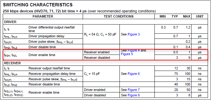
The spec I've circled seems to assume the receiver is either enabled or disabled.  Now one interpretation might be that this is referring to the initial condition, and so in my case my "steady state" has the receiver enabled.  Therefore I should expect a maximum driver enable time of 1us.  On the other hand, since both signals are transitioning I need to be sure that I'm not going to see a delay of 9us.  At 115.2 kbaud that would be an entire bit time!

For further background, this actually relates to my other thread I posted about "auto direction" transceivers.  Another avenue I'm pursuing is to simply tie the TXD input of the transceiver to a fixed state, add pullups on the outputs, and use the UART's Tx signal (inverted) to drive the DE/RE# pins.  In this scenario when I transmit data from the UART the DE/RE# pins will be toggling at the UART baud rate so I need to be sure the transitions seen on the RS-485 bus can keep up.

  • Hi Brad,

    I agree with the interpretation that the initial condition of receiver enabled will determine the driver enable time. To be sure, though, I will take one into the lab and test it out. I'll let you know how it goes.

    Thanks!
    Jason Blackman 

  • Hi Brad,

    I just verified that when DE and RE are tied together, the driver enable time falls into the fast 'receiver enabled' category, as we expected.

    Let me know if you have any more questions!

    Thanks,
    Jason Blackman 

  • This is very good info.  However, can you share any more details on what exactly controls which "bucket" the timing falls into?  Although your test is promising, how do we know this is applicable across all process/voltage/temperature?

  • Hi Brad,

    I spoke with the designer and confirmed that this is the expected behavior across process, voltage and temperature. The distinction between the long and short enable times is whether or not the receiver has had enough time to fully enable or not. For example, if the driver is disabled when the receiver gets enabled, the receiver will take 3us typical to fully enable. If the driver is enabled within that window, it will be slow, but if it happens after that 3us window, then it will be fast. 

    When the DE and RE pins are tied together, there is no offset where either RX or TX wouldn't have enough time to fully enable before the other signal gets enabled. It will always be the fast enable time.

    Hope this helps!
    Jason Blackman