This thread has been locked.

If you have a related question, please click the "Ask a related question" button in the top right corner. The newly created question will be automatically linked to this question.

DS110DF410 How to View Eye monitor by external software ?

Other Parts Discussed in Thread: DS110DF410

Hi
Please let me confirm some questions about DS110DF410.

My Custmer want to try viewing an eye diagram by external software.

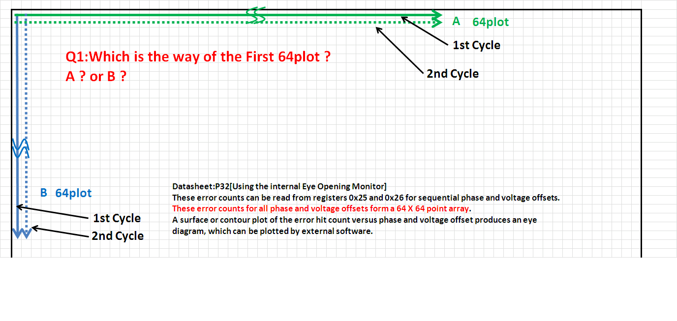
Regarding to the Datasheet of DS110DF410 on page P32, Method: [Using the internal Eye Opening Monitor]
"A surface or contour plot of the error hit count versus phase and voltage offset produces an eye diagram, which can be plotted by external software."

I understood that by referring to the data stored in the 0x26 and 0x25, to be able to draw the eye diagram.

The error count data that they have read, Where start from any position in the 64 * 64?
Please refer to the Appendix.

Best regards

Sugiyama

  • Sugiyama-San,

    I apologize for the delay.

    It is B. 

    I am working on putting together a procedure for measuring EOM. I am hoping to have this posted in 1-2 days.

    Regards,,nasser

  • Hi nasser-san

    Thank you for the Answer .

    And , I'm looking for post procedure manual of EOM.

    Best regards

    Sugiyama

  • Sugiyama-San,

    Here are the procedure for Fast Eye Capture that i was discussing earlier. Please note these are read/modify write:

    1). Select the channel to be used for the EOM by using appropriate channel using register 0xff

    2). Disable HEO and VEO Lock monitor by writing 0 into register 0x3e bit 7

    3). Select the voltage range by using bits 7:6 of register 0x11. Based on the eye opening, this voltage range may need to be changed to capture the eye hits. To make sure we would be able to capture the eye hits one may try to use the highest range first(for example +/-400mV)

    4). Enable the eye opening monitor by clearing register 0x11 bit 5 (EOM_PD).

    5). Clear register 0x22 bit 7 the eom_ov_bit. In default mode this is 1 and it should be set to 0 for EOM readings

    6). Enable fast EOM mode by setting register 0x24 bit 7 (FAST_EOM).

    7). Set register 0x24 bit 0 eom_start

    8). Read back register 0x24 bit 0 and wait until it is cleared

    9). Read the most significant 8 bits from register 0x25 bits 7:0 and throw away this value

    10). Read the lest significant 8 bits from register 0x26 bits 7:0 and throw away this value

    11). Read the most significant 8 bits from register 0x25 bits 7:0 and throw away this value

    12). Read the lest significant 8 bits from register 0x26 bits 7:0 and throw away this value

    13). Read the most significant 8 bits from register 0x25 bits 7:0 and store this value

    14). Read the least significant bits from register 0x26 bits 7:0 and store this value

    15). Do steps 13 & 14 4096 times to read in 4096 16 bits values and store these values. The first 64 X 16 bits are the vertical hits, and the second 64X16 are the second column and this has to be done for a total of 64 times(i.e 64X64X16bits).

    16). Disable FAST_EOM by writing 0 to bit 7 of register 0x24

    17). Allow CDR state machine to control the EOM by setting bit 5 of register 0x11

    18). Enable HEO/VEO lock monitoring by setting bit 7 of register 0x3e

    Regards,,nasser

  • Nasser-san,

    Thank you very much for your great support.

    At present, our customer still cannot change the voltage range for EOM.

    Question)
    Would there be a possibility that if the customer does not  change the register with "Read/Modify Write", voltage  range could not be set correctly ?
    As our customer has all the default register value including undefined bits, they are not doing Read/Modify Writes.

    -----

    We also have another question.

    Question)
    Do you need some WAIT time between reading ADR 0x25 and ADR 0x26 continuously ?

    Best Regards,
    Kawai

  • Kawai-San,

    The customer MUST do read/modify write since some of the bits may change the CDR state machine or have other functions. However, i cannot say 100% this is the reason they are not able to change voltage range. Please ask the customer to change all of their register access to read/modify write. Once this is done, if they still have this problem please send us all of their register content or list of the registers they are changing plus the content and we can do futher debugging.

    Regards,,nasser

  • Nasser-san,

    There were no change by programming with "Read/Modify Write".

    I will send you our customer's data (Register dump, EOM waveform, other ). As I cannot upload these files to the public E2E, could you please let me contact you directly ?

    I appreciate if you could give me an Email.

    Best Regards,
    Kawai