This thread has been locked.

If you have a related question, please click the "Ask a related question" button in the top right corner. The newly created question will be automatically linked to this question.

DS92LX1621 and DS92LX1622 GPIO

Other Parts Discussed in Thread: DS92LX1622, DS92LX1621, LX16EVK01, DS91C176EVK

Hi,

I got the Evaluation Board LX16EVK01 with the Serdes DS92LX1621 and DS92LX1622.

I used the following DIP switch settings:

DS92LX1621: RESO = LOW

                          M_S = LOW

                          PDB = HIGH

DS92LX1622: RESO = LOW

                          M_S = HIGH

                          BIST = LOW

                          PDB = HIGH

According to the Manual of the Evaluation Board there is no need to change the Software Settings of the Serdes to get a uplink connection via the GPIO[0] Pin (lowspeed uplink from DS92LX1622 to DS92LX1621). 

But for any reason i cant get a uplink. Can you tell me whats wrong in these Settings?

By the way the PASS LED lights up. 

  • Hi Viktor,

    Based on your description, the device is setup in camera mode. Have you performed the remote wake up procedure as described in the DS92LX1621/2 datasheet on page 34? By default, the SER is in low power standby mode until the DES remote awakes the device. Following the remote wake up initialization, you should monitor the LOCK pin (LED lit) ensure the DES has acquired lock. Afterwards, you will be able to transmit data across the GPIO[0] pin.

    Dac Tran

    SVA APPS

  • I followed the steps on page 34, but there is still no uplink on the GPIO[0] pin (PASS LED lit).

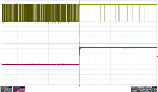
    Before the last step on page 34 is done (Return the control channel driver of the DES...) there is a reaction on the GPIO[0] pin. The following screenshot shows the reaction.

    The bottom Signal is the input GPIO[0] pin at the DES. 

    The upper Signal represents the answer of the SER at GPIO[0] pin.

    Normally the upper Signal should look like the bottom Signal.

    The PASS LED is still lit up at this moment.

  • Hi Viktor,

    After following the remote wake up procedure on page 34, does the LOCK (LED2) light up? PASS LED is always lit and only valid under BIST modes.

    Dac Tran

    SVA APPS

  • Hi Dac Tran,

    the LOCK LED doesn't light up.

  • Hi Viktor,

    The LOCK needs to be on in order for the GPIOs to function. Can you get any LOCK status when you configure serdes in display mode (1621 MS=H and 1622 MS=L)?

    Dac Tran

    SVA APPS

  •  Hi Dac Tran,

    the Problem has been solved. I haven't said that I also use a RJ45 to SMA Adapter Board (DS91C176EVK).

    The unidirectional communication worked without problems. But the bidirektional channel has been blocked by the additional resistor between the differential pair (R8).

    Nevertheless thank you for your efforts.