This thread has been locked.

If you have a related question, please click the "Ask a related question" button in the top right corner. The newly created question will be automatically linked to this question.

ISO5500: output and configuration problem

Hi,

I'm having problems getting the ISO5500 to work as described in the datasheet.

I'm trying to use this module to amplify a 0~5V PWM signal from a microcontroller (PIC16F) to a -10/+10V voltage level, in order to interface with another DC motor driver that accepts -10/+10V analog input. I realized of course that I could only amplify successfully to a -12/+12 V because of the UVLO constraint on (Vcc2 - Ve).

The inputs to Vin+ and Vin- are two PWM outputs from the PIC in differential signal form. eg pwmA: 0~5V, pwmB:0V. The idea is to interchange between which channel is active in order to create both negative and positive PWM output. Vcc1 and GND1 are 5V 0V respectively. Vcc2 is say, 24V relative to GND2 (i.e. Vee-l, Vee-p), and I just set up the circuit from fig.62 of the data sheet.

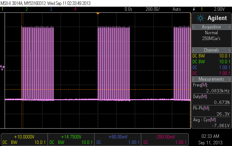
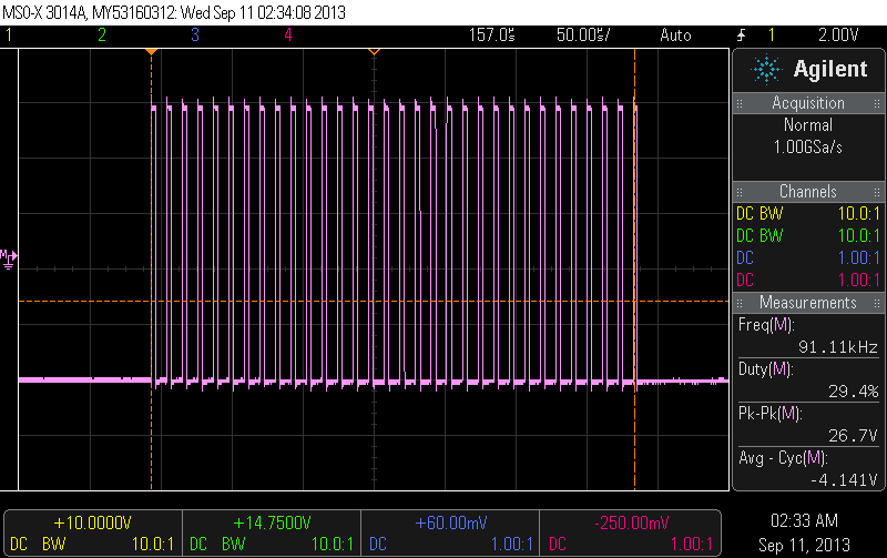
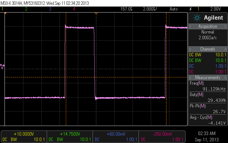
Firstly, I'm observing on my oscilloscope, that the ouput waveform is not the input with amplification. In fact the output seems to be modulated by a chopping frequency of a about 92KHz. The input PWM has 42% duty at 1.2KHz, and ony on very large time scales does the oscilloscope show this. Where does the chopping frequency originate from? The datasheet makes no mention of this.

Secondly, the average value on the output is nowhere near the intended value. In fact, despite having the voltage levels at (relatively) expected levels, the average value shown by the oscilloscope is the negtive ouput rail (-12V relative to Ve).

I know this is not its intended function, but from the datasheet I surmised that it would be feasible to create the intended amplification. If there are any suggestions either using the ISO5500 or even any other topology it would prove invaluable. I have been at this for almost 3 weeks straight and I cant seem to make it work.

The reasoning for not using just an op-amp topology is that i require differential input with high input resistance and also need differential output. The only solution close to this was a instrumntation amp circuit, but I could only achieve said waveform by connecting the PIC gnd to the 10V ref ( so that input common was at 10V so op-amps could function properly). Because of the requirement for isolation I came by the ISO5500.

Thanx. 

  • Hi Vasileios, 

    I'm not sure what you're trying to do with multiple PWM signals. You don't need positive and negative waveforms to have the output toggle between Vcc2 and Vee-p. If you simply tie Vin- low and send a 0-5V PWM into Vin+, the output will be high when Vin+ is high and low when Vin- is low.

    If I'm missing something about your setup, please explain further. If you could share some scope shots of the input and output, that would be helpful.

    Thanks,
    Jason Blackman 

  • Hi Jason,

    Thank you for the prompt reply. Some industrial motor drivers accept onily analog  [-10,+10]V input in order to drive the motor currents. In my case I'm to control a MAXON ads 50/5 motor driver. 

    http://test.maxonmotor.com/docsx/Download/Product/Pdf/ads50-5_en.pdf

    Unlike other motor drivers where the inputs are 1ch PWM and 1ch DIR (direction). In other cases you can use two PWM channels for the following functionality. By taking as differential input, Vin(diff) =  PWMA(Vin+) - PWMB(Vin-), you can achieve both counter clock wise and clock wise directions for the motor by(e.g.):

    CCW: PWMA = 42% duty , PWMB = 0% duty

    CW: PWMA = 0%, PWM = 42% duty.

    This way, in CCW you have a PWM in the [0, +10]V range and in CW [-10,0] range. All of these relative to the output common-mode/reference of course.

    If i can amplify this differential signal then you can control the motor in both directions without degrading voltage resolution (from the register controlling the PWM period/frequency in the microcontroller)

    These are the outputs I'm viewing on my oscilloscope(agilent MSOX3014A)

     http://www.home.agilent.com/en/pd-1947946-pn-MSOX3014A/oscilloscope-100-mhz-4-analog-plus-16-digital-channels?&cc=GR&lc=eng)

    Input signal:

    Output(Vout(diff) = Vout - Ve, on ISO5500)  in decreasing time scales(zooming in):

    Vout is clearly modulated by the 90KHz and the mean value(which is exactly what I want to control as a function of Duty cycle) are clearly not the desired.

  • From what you've described, I don't think this part will work for you. It will only output either Vcc2 or Vee-p, so it will be a big square wave from -10V to +10V in your case. It sounds like you are interested in having a PWM between 0V and +10V, or between 0V and -10V. Please correct me if I'm wrong.

    That being said, I'm not sure about the behavior you are witnessing. Do you have Vin- at 0V and the PWM signal (shown) at Vin+? Can you check the FAULT pin and see if it is doing anything?

    Thanks,
    Jason 

  • The thing is even one big square wave is fine as long as it is the same frequency and  duty as the input. In this case i can just have 50% duty as zero mean i.e zero motor current, below 50% can be CW and above can be CCW. my main problem is the distorted output. the fault pin is pulled-up to Vcc1(+5V) by a 3.3KOhm resistor, and I found that the output appears only when RESET is at GND1 directly. Also it does not output -10/+10 because if (Vcc2 - Ve) is below 12.3V according to the datasheet, then UVLO function disables the output(is held low). This is the reason I increased Vcc2 to 24V and connected Ve to +12V(as reference for Vo). Is there any way to bypass this so I can get it to work at -10/+10V? I think the chopper is the cause for the wrong mean value, but I don't understand why it happens in the first place.